Actuator
- Summary
- Abstract
- Description
- Claims
- Application Information
AI Technical Summary
Benefits of technology
Problems solved by technology
Method used
Image

Examples
first modification of embodiment 1
[0078]FIG. 5 is a schematic view illustrating the structure of a stationary element 200A according to a first modification of Embodiment 1 of the present invention.
[0079]Referring to FIG. 5, in an actuator using the stationary element 200A according to this modification, the actuator is driven in a state where a current is varied by cyclically turning ON / OFF a voltage applied to the piezoelectric members 204a and 204b which are the strainable members. More specifically, in the actuator using the stationary element 200A, a DC voltage source 259 for generating a predetermined DC voltage and a switch unit SW are disposed, instead of the AC voltage source 208 (FIG. 4), between the shim member 202 and each of the surface electrodes 206a and 206b. In response to a cyclic switching command from a controller (not shown), the switch unit SW cyclically turns ON / OFF (intermittently supplies) the DC voltage that is applied to the piezoelectric members 204a and 204b from the DC voltage source 25...
third modification of embodiment 1
[0094]FIG. 8 is a schematic view illustrating the structure of a stationary element 250 according to a third modification of Embodiment 1 of the present invention.
[0095]Referring to FIG. 8, the stationary element 250 according to this modification includes an electrically conductive core portion 252, and a clad portion 256 formed in a concentric form around the core portion 252. The clad portion 256 is made of, e.g., a piezoelectric member, an electrostrictive member, or a dielectric member, and it causes a displacement by receiving an internal electric field that is generated upon application of a voltage. The core portion 252 is made of, e.g., a polymer mixed with a metal or an electrically conductive filler. The piezoelectric member, the electrostrictive member, or the dielectric member, which is used to form the clad portion 256, is made of a ceramic, a polymer, or a composite (mixed) material of them.
[0096]Electrodes 254a and 254b electrically connected to the core portion 252 ...
embodiment 1
Advantages Obtained with Embodiment 1
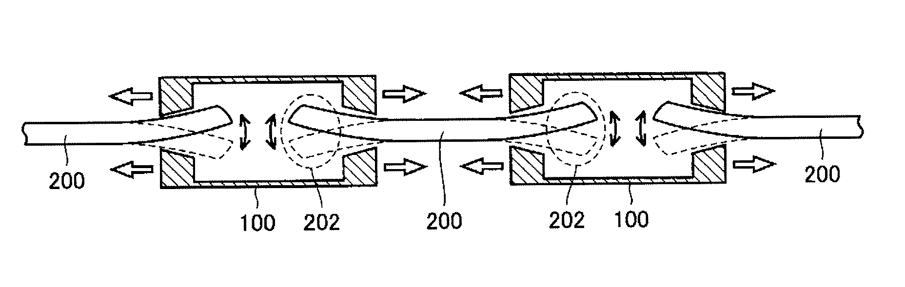
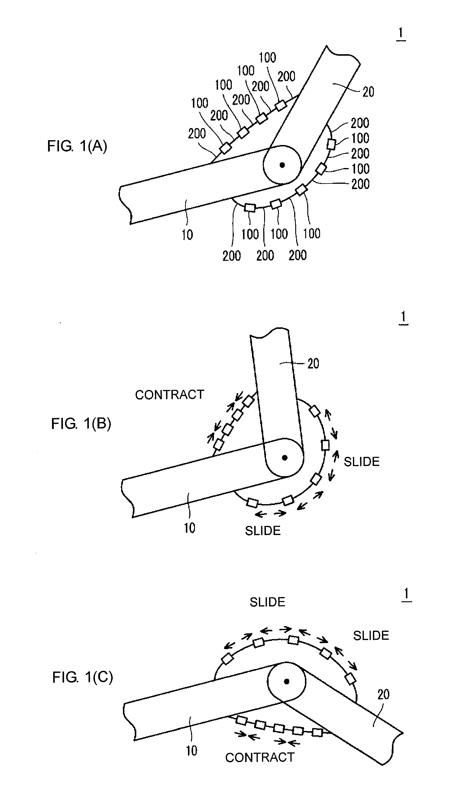
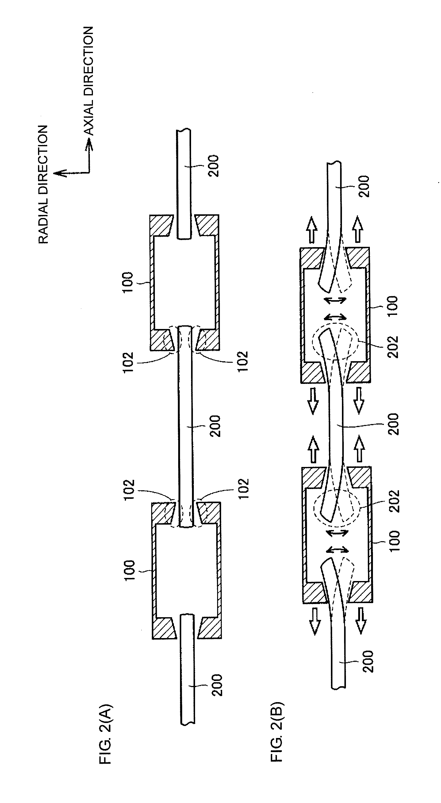
[0100]According to Embodiment 1 of the present invention, when the actuator is driven, the stationary element causes a displacement at least in the radial direction such that the stationary element is relatively retracted into the corresponding movable elements, whereby the contracting operation is performed between the adjacent movable elements. When the actuator is not driven, the movable element and the stationary element can be moved relative to each other by receiving a slight force applied from the exterior. As a result, behaviors similar to operations of muscles of an organism can be realized.
[0101]Also, according to Embodiment 1 of the present invention, since a static frictional force between the movable element and the stationary element is small, a wear caused during the driving can be reduced. As a result, the life span of the actuator can be prolonged.
Embodiment 2
[0102]While Embodiment 1 has been described above, by way of example, i...
PUM
 Abstract
Description
Claims
Application Information
 - R&D Engineer
- R&D Manager
- IP Professional
- Industry Leading Data Capabilities
- Powerful AI technology
- Patent DNA Extraction
Browse by: Latest US Patents, China's latest patents, Technical Efficacy Thesaurus, Application Domain, Technology Topic.
© 2024 PatSnap. All rights reserved.Legal|Privacy policy|Modern Slavery Act Transparency Statement|Sitemap