Fiber ribbon and fiber ribbon attached to connector for wiring in equipment

a technology of optical fiber ribbon and connector, which is applied in the direction of optics, fibre mechanical structures, instruments, etc., can solve the problems of fragile silicone resin and difficult pulling out the outer, and achieve the effect of easy and satisfactorily being exposed

Inactive Publication Date: 2010-10-07
SUMITOMO ELECTRIC IND LTD
View PDF3 Cites 13 Cited by
  • Summary
  • Abstract
  • Description
  • Claims
  • Application Information

AI Technical Summary

Benefits of technology

[0007]The object of the present invention is to provide an optical fiber ribbon for wiring of equipment and an optical fiber ribbon attached to connector for wiring of equipment. In the optical fiber ribbon of the invention, the inner fiber coating layer can easily and satisfactorily be exposed by removing the collective coating and the outer fiber coating layer at a stretch.

Problems solved by technology

H 2-151821 are further covered with a collective coating, the attempt to remove the outer fiber coating layer together the collective coating will often result in failure: it is difficult to pull out the outer fiber coating layer in a clean layer condition, that is, the residues of the silicone resin might be left on the inner fiber coating layer.
This is because the silicone resin is fragile.

Method used


Image

  • Fiber ribbon and fiber ribbon attached to connector for wiring in equipment
  • Fiber ribbon and fiber ribbon attached to connector for wiring in equipment
  • Fiber ribbon and fiber ribbon attached to connector for wiring in equipment

Examples


examples

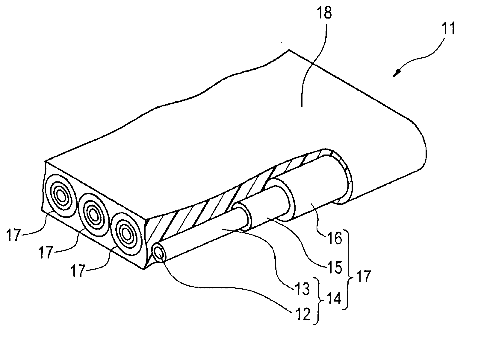
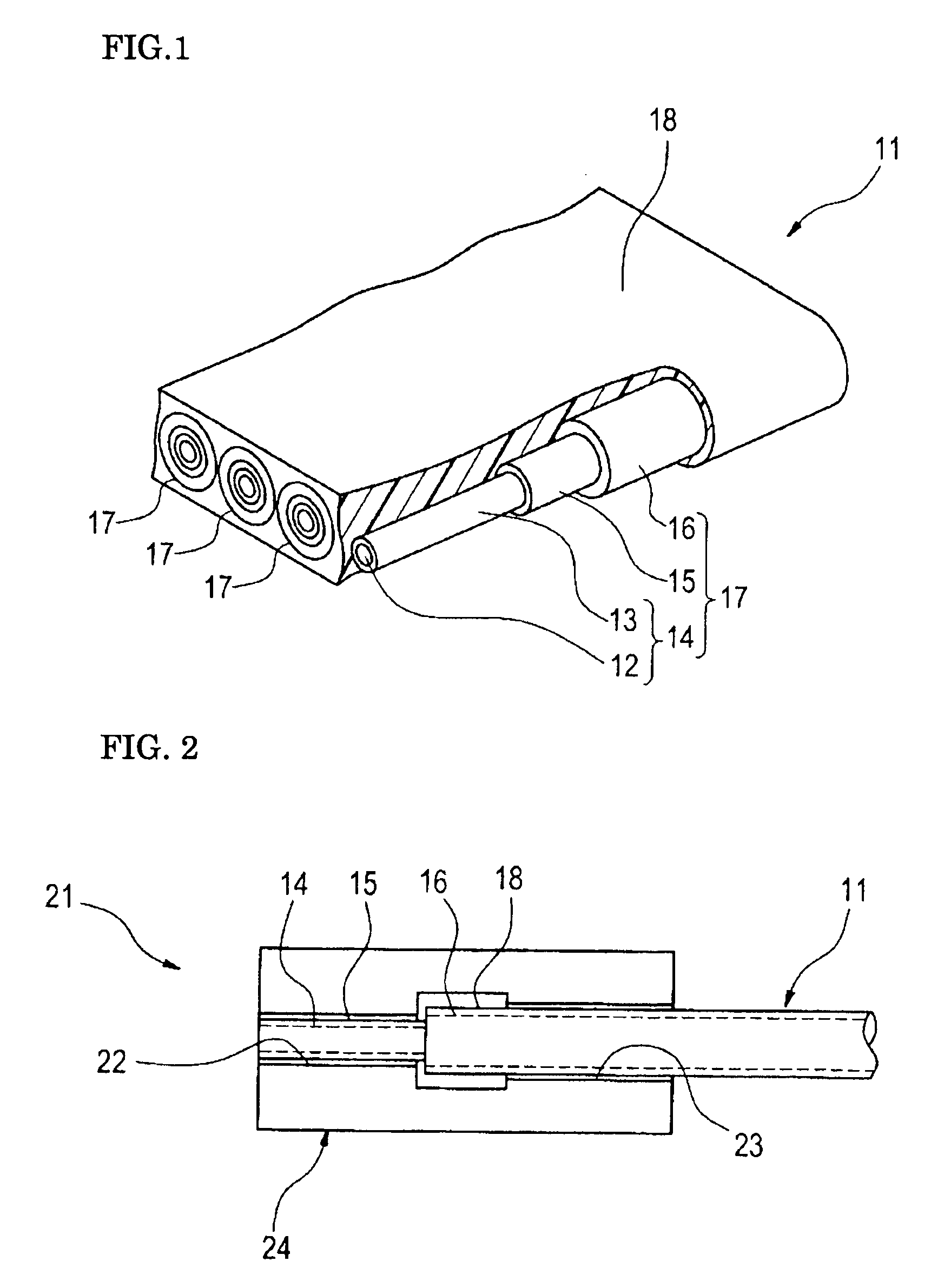
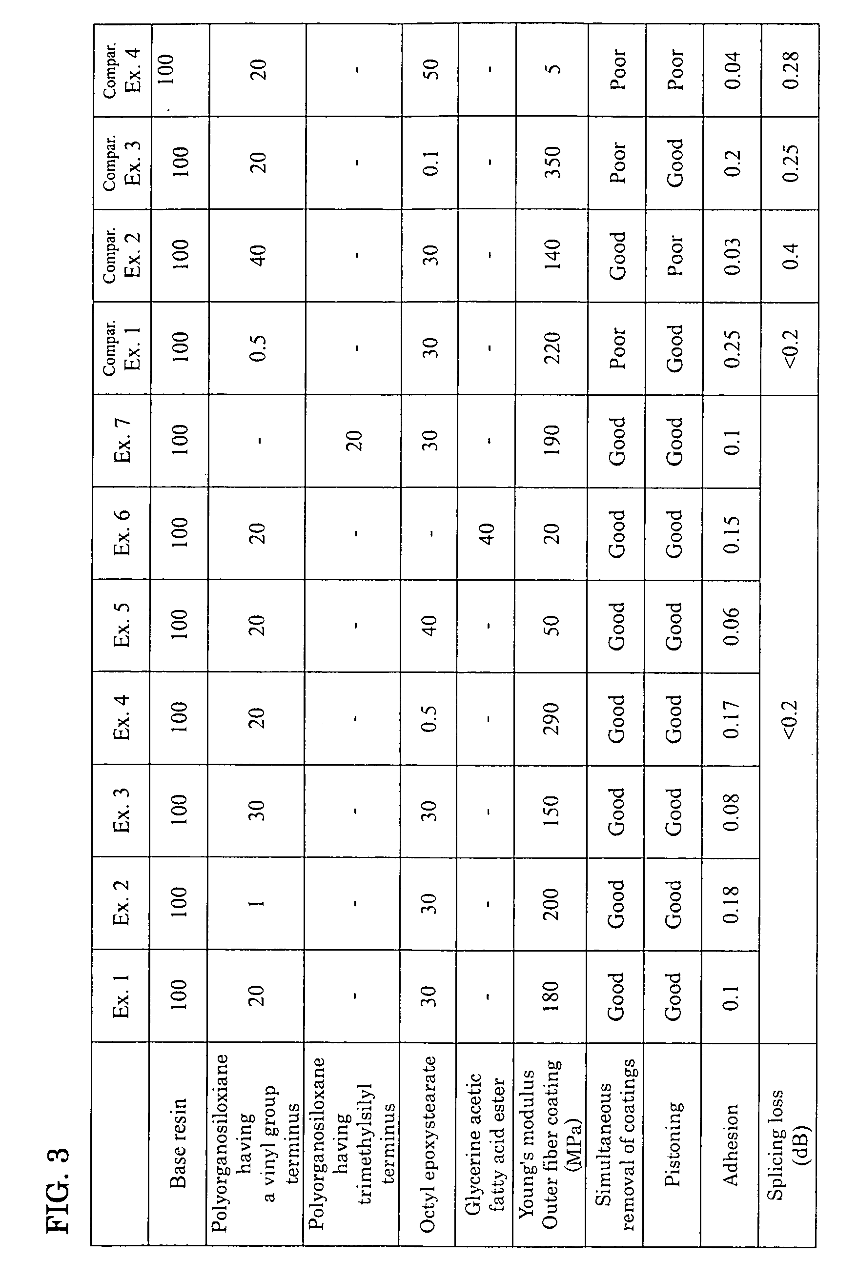
[0036]FIG. 3 is a table showing the mixing ratios of additives added to the base resins of the outer fiber coating layers and the respective evaluation results in Examples 1 to 7 and Comparative Examples 1 to 4. The optical fiber ribbons (Examples 1 to 7 and Comparative Examples 1 to 4) covered with the resins having the compositions shown in FIG. 3 are prepared and the respective characteristics are evaluated. In a glass fiber included in an optical fiber ribbon, the relative refractive index difference Δn of the core 12 and the cladding 13 is 1.9%. The resins are made by adding the additives described in the table to the base resin, which is made from 84 wt % of oligomer, 5 wt % of monomer 1 (N-vinyl caprolactam), 5 wt % of monomer 2 (isobornyl acrylate), 5 wt % of monomer 3 (2-hydroxypropyl acrylate), and 1 wt % of optical initiator (Lucirin TPO), whereas the oligomer is prepared by mixing polypropylene glycol (PPG) having a number average molecular weight of 3500, toluene-diisoc...


PUM


Abstract

When a glass fiber and an inner fiber coating layer are to be attached to a connector by removing an outer fiber coating layer while leaving the inner fiber coating layer as it is, a collective coating and the outer fiber coating layer can be removed at a stretch so that the inner fiber coating layer can easily and satisfactorily be exposed. In the ultraviolet curable resin coating layer of a coated optical fiber 17 of an optical fiber ribbon 11 for wiring of equipment, the inner fiber coating layer 15 has a Young's modulus of 600 MPa to 1000 MPa, and the outer fiber coating layer 16 has a Young's modulus of 10 MPa to 300 MPa. The material of the outer fiber coating layer 16 is made by mixing 100 weight parts of base resin, 1-30 weight parts of silicone-based additive, and 0.5 to 40 weight parts of long chain fatty acid ester compound, wherein the base resin is a material made of a urethane metha acrylate oligomer, a mono-functional or multi-functional reactive dilution monomer, and an optical initiator.

Description

BACKGROUND OF THE INVENTION[0001]1. Field of the Invention[0002]The present invention relates to an optical fiber ribbon for wiring of equipment and a connector-attached optical fiber ribbon for wiring of equipment.[0003]2. Description of the Background Art[0004]The optical fiber ribbon is made by arranging a plurality of coated optical fibers in parallel and covering them with a collective coating so as to make an integral ribbon-like form. Japanese Patent Application Publication No. 2003-95706 describes coated optical fibers contained in an optical fiber ribbon. The coated optical fiber is such that the outer circumferential surface of a glass fiber is coated with two layers made of ultraviolet curable resin: an inner fiber coating layer and an outer fiber coating layer. The inner fiber coating layer has Young's modulus of about 1.2 MPa, and the outer fiber coating layer has Young's modulus of about 700 to 750 MPa, and the outer fiber coating layer is harder than the inner fiber c...

Claims


Application Information

Patent Timeline
Patent Type & Authority Applications(United States)
IPC IPC(8): G02B6/40G02B6/44
CPCG02B6/443G02B6/4403
Inventor TANAKA, KAZUNORIOISHI, KAZUMASAHATTORI, TOMOYUKIHARUNA, TETSUYASAKURAI, WATARUTAMURA, MITSUAKISAITO, KAZUTO
Owner SUMITOMO ELECTRIC IND LTD
Why Eureka
Try Eureka