Scroll compressor

a fluid displacement apparatus and scroll technology, applied in the direction of machines/engines, rotary/oscillating piston pump components, liquid fuel engines, etc., can solve the problems of difficult engagement and the increase of the manufacturing cost of the typical scroll type fluid displacement apparatus, and achieve easy and quick coupling, easy and quick secured or assembled

Active Publication Date: 2010-10-07
CHU HENRY C
View PDF16 Cites 4 Cited by
  • Summary
  • Abstract
  • Description
  • Claims
  • Application Information

AI Technical Summary

Benefits of technology

[0012]The primary objective of the present invention is to provide a scroll compressor including a fluid inlet and a fluid outlet disposed or arranged rearwardly or at the rear portion of the compressor for allowing the compressor to be easily and quickly coupled to the tubings or pipings of the vehicle with the other tubings or pipings without bending or folding the other tubings or pipings, and for allowing the compressor to be easily and quickly secured or assembled or mounted within the tiny engine chamber of the vehicle.

Problems solved by technology

However, in the tiny engine chamber of the vehicle, it will be difficult to engage the tubings or pipings into the tiny engine chamber and to couple the other tubings or pipings to the fluid inlet and the fluid outlet of the compressor housing, and it is required to bend or fold the other tubings or pipings before the fluid outlet of the compressor housing may be coupled to the tubings or pipings of the vehicle.
However, the inner structure of the compressor housing should be greatly or vastly changed or modified to form the gas flowing passage within the inner portion of the compressor housing, such that the whole typical scroll type fluid displacement apparatus should be redesigned and manufactured, and such that the manufacturing cost for the typical scroll type fluid displacement apparatus will be greatly increased.

Method used


Image

  • Scroll compressor
  • Scroll compressor
  • Scroll compressor

Examples


Embodiment Construction

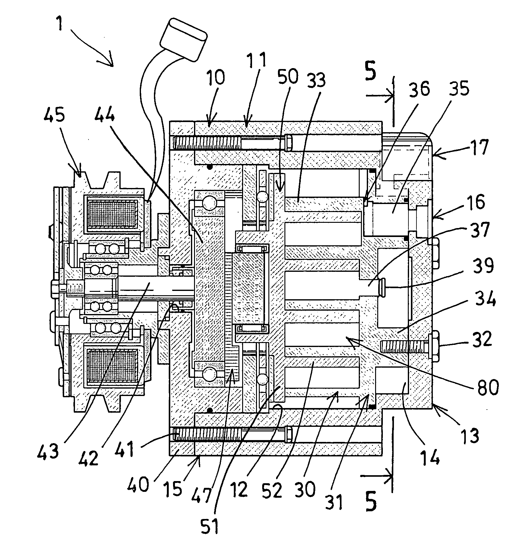
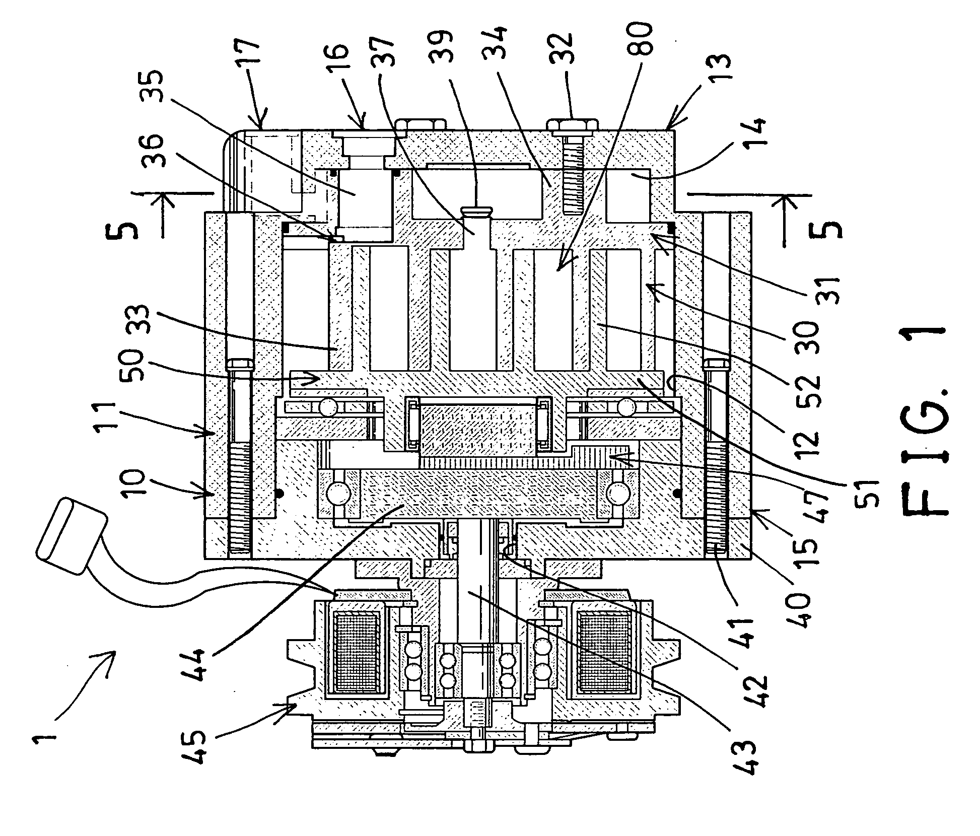
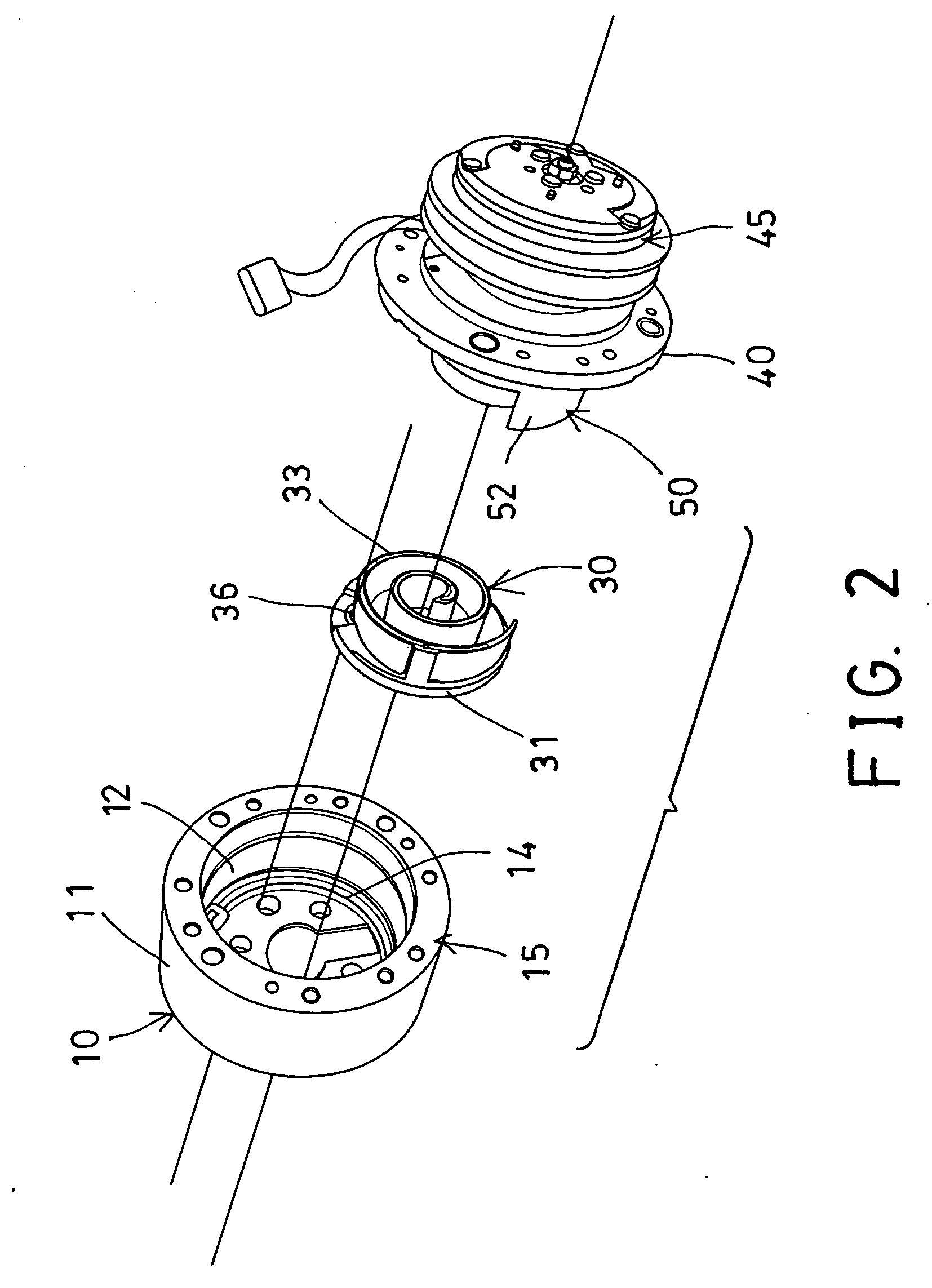
[0024]Referring to the drawings, and initially to FIGS. 1-5, a scroll compressor 1 in accordance with the present invention comprises a compressor housing 10 including a cup shaped casing 11 having a chamber 12 formed in the cup shaped casing 11, and having a rear portion or rearward end 13, and having a compartment 14 formed in the rearward end 13 and communicating with the chamber 12 of the casing 11. A fixed scroll 30 is mounted within the chamber 12 of the cup shaped casing 11, and includes a base plate 31 fixed to the casing 11 with one or more latches or fasteners 32, and includes a spiral scroll element 33 extended outwardly from the base plate 31 and disposed and located within the chamber 12 of the casing 11.

[0025]A front end plate 40 is attached or mounted to the front portion 15 of the casing 11 with one or more latches or fasteners 41 for closing the chamber 12 of the casing 11, and includes an orifice 42 formed in the center portion thereof for rotatably receiving or su...


PUM


Abstract

A scroll compressor includes a chamber formed in a casing and a compartment formed in a rearward end, a fixed scroll mounted within the casing and having a spiral scroll element extended from a base plate, and an orbiting scroll rotatably disposed in the casing, and having a spiral scroll element extended from a carrier plate and arranged to form a line contact between the spiral scroll elements, and the fixed scroll includes an inlet mouth and a fluid passage formed through the base plate, and the casing includes an inlet port and an outlet port formed in the rearward end for easily and quickly coupling to the tubings of the vehicle with pipings without bending or folding the pipings.

Description

BACKGROUND OF THE INVENTION[0001]1. Field of the Invention[0002]The present invention relates to a scroll type fluid displacement apparatus, and more particularly to a scroll type compressor including a fluid inlet and a fluid outlet disposed or arranged rearwardly or at the rear portion of the compressor for allowing the compressor to be easily and quickly coupled to the tubings or pipings of the vehicle with the other tubings or pipings without bending or folding the other tubings or pipings, and for allowing the compressor to be easily and quickly secured or assembled or mounted within the tiny engine chamber of the vehicle.[0003]2. Description of the Prior Art[0004]Typical scroll compressors comprise a compressor housing including a front end plate member attached to the upper portion of a cup shaped casing, a fixed scroll member mounted within the cup shaped casing, and an orbiting scroll member rotatably disposed within the inner chamber of the cup shaped casing and disposed o...

Claims


Application Information

Patent Timeline
Patent Type & Authority Applications(United States)
IPC IPC(8): F04C18/02F04C27/00
CPCF04C18/0215F04C29/0064F04C29/122F04C2240/30F04C2230/70F04C2230/80F04C2230/60
Inventor CHU, HENRY C.
Owner CHU HENRY C
Why Eureka
Try Eureka