Coaxial cable connector with improved physical and RF sealing

a technology of rf sealing and coaxial cable, which is applied in the direction of connection, electrical apparatus, coupling device connection, etc., can solve the problems of component abutment and rf sealing loss, cable connection may also be faulty, and connectors are not properly installed to the interface por

Active Publication Date: 2010-10-07
PPC BROADBAND INC
View PDF99 Cites 170 Cited by
  • Summary
  • Abstract
  • Description
  • Claims
  • Application Information

AI Technical Summary

Benefits of technology

[0005]A second aspect of the present invention provides an F-type coaxial cable connector for coupling a coaxial cable to an interface port, the coaxial cable including a center conductor surrounded by a dielectric material, the dielectric material being surrounded by an outer conductive grounding shield, the outer conductive grounding shield surrounded by a protective outer jacket, the F-type coaxial cable connector comprising in combination: a connector body, having a first end and a second end, the second end configured to deformably compress against and seal a received coaxial cable; a post, axially securely attached to the connector body, the post having a first end and a second end, the first end of the post including a flange and the second end of the post configured to be inserted into an end of the received coaxial cable around the dielectric and under at least one layer the conductive grounding shield thereof; a threaded nut, rotatable with respect to the post and also axially movable with respect to the connector body between a first position and a second position; a biasing member, the biasing member compressably operable to exert force on the nut tending the nut to move in a direction toward the second end of the connector body; a fastener member, including an internal ramped surface, the fastener member operable to deformably compress the outer surface of the connector body to axially secure the received coaxial cable between the connector body and the fastener member; and a joint stop element, including obstructive structure of a component of the connector that is axially movable with respect to the received and secured cable and including obstructive structure of a component that is not movable with respect to the received and secured cable; wherein the obstructive structure of the movable component with respect to the cable contacts the obstructive structure of the non-axially-movable component with respect to the cable when the nut is in a second position to impede axial movement of the nut in a direction toward the first end of the connector body.
[0006]A third aspect of the present invention provides an F-type coaxial cable connector comprising: a connector body; a post, attached to the connector body; a threaded nut, rotatable with respect to the post and also axially movable with respect to the connector body between a first position and a second position; a biasing member, operable to exert force on the nut to move the nut; and means for impeding axial movement of the nut in one axial direction, when the nut resides in the second position; wherein the means remain structurally sound during the buildup of axial force applied thereto, as threadable rotational torque is exerted when the nut is tightened into mating with a corresponding interface port, through operation of a wrench; and wherein the means prevent the connector from experiencing structural and functional deformation because the movement impediments of the means prevent the biasing member from being over-compressed causing connector components to yield and thus not properly function during repetitive use.
[0007]A fourth aspect of the present invention provide a method of extending an RF grounding shield from a coaxial cable to a cable interface port, the method comprising: providing an F-type coaxial cable connector to connect the coaxial cable to the interface port, the F-type coaxial cable connector comprising: a connector body, having a first end and a second end; a post, attached to the connector body and operable to receive the coaxial cable; a threaded nut, rotatable with respect to the post and also axially movable with respect to the connector body between a first position and a second position; a biasing member, operable to exert force on the nut tending the nut to move in a direction toward the second end of the connector body; a fastener member, including an internal ramped surface, the fastener member operable to deformably compress the outer surface of the connector body to axially secure the received coaxial cable between the connector body and the fastener member; and a joint stop element, located to interact with the biasing member and introduce obstructive structure that impedes axial movement of the nut; wherein the nut is movable in an axial direction toward the first end of the connector body when in a first position; and wherein the nut is not movable in a direction toward the first end of the connector body when in a second position, because the obstructive structure of the joint stop element physically impedes further movement of the nut; rotating the nut to thread the nut onto the interface port a distance sufficient for the post of the connector to contact the port, wherein the position of the connector structure when the post initially contacts the port corresponds to a first position; advancing and tightening the nut further onto the port to ensure electrical contact between a mating edge of the port and a mating edge of the post, wherein, as the nut advances onto the port it axially slidably moves with respect to the post and connector body in a direction toward the first end of the connector body, so that the associated biasing member exerts resultant force to drive the post into firm contact with the interface port; and impeding further axial movement of the nut with respect to the post and the connector body, by bottoming out the movement of the nut through operation of obstructive structure of the joint stop element so that the bottoming out of the movement of the nut corresponds to a second position, wherein the nut is no longer axially movable in a direction toward the first end of the connector body.

Problems solved by technology

However, often connectors are not properly installed to the interface port.
Once tightened, the connector may loosen causing loss of component abutment and RF sealing.
The cable connection may also be faulty because the connector is over-tightened onto the interface port causing connector components to yield and / or move out of proper physical and RF sealing connection with the interface port.
Furthermore, common connectors do not facilitate both RF sealing and also physical sealing against ingress of physical environmental contaminants that may enter the connector and cause a faulty connection or otherwise hinder connector performance.

Method used


Image

  • Coaxial cable connector with improved physical and RF sealing
  • Coaxial cable connector with improved physical and RF sealing
  • Coaxial cable connector with improved physical and RF sealing

Examples


Embodiment Construction

[0024]Although certain embodiments of the present invention are shown and described in detail, it should be understood that various changes and modifications may be made without departing from the scope of the appended claims. The scope of the present invention will in no way be limited to the number of constituting components, the materials thereof, the shapes thereof, the relative arrangement thereof, etc., and are disclosed simply as an example of embodiments of the present invention.

[0025]As a preface to the detailed description, it should be noted that, as used in this specification and the appended claims, the singular forms “a”, “an” and “the” include plural referents, unless the context clearly dictates otherwise.

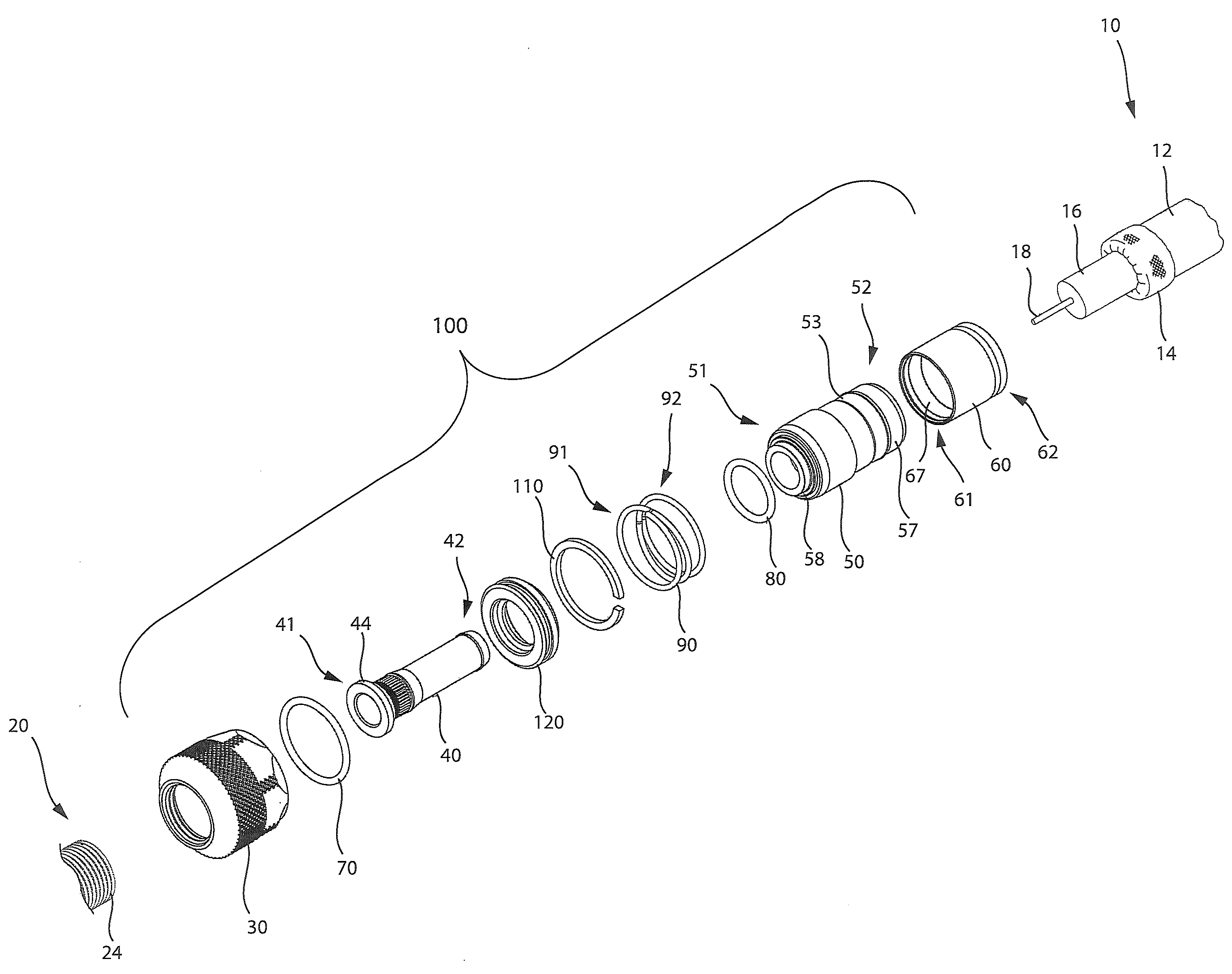
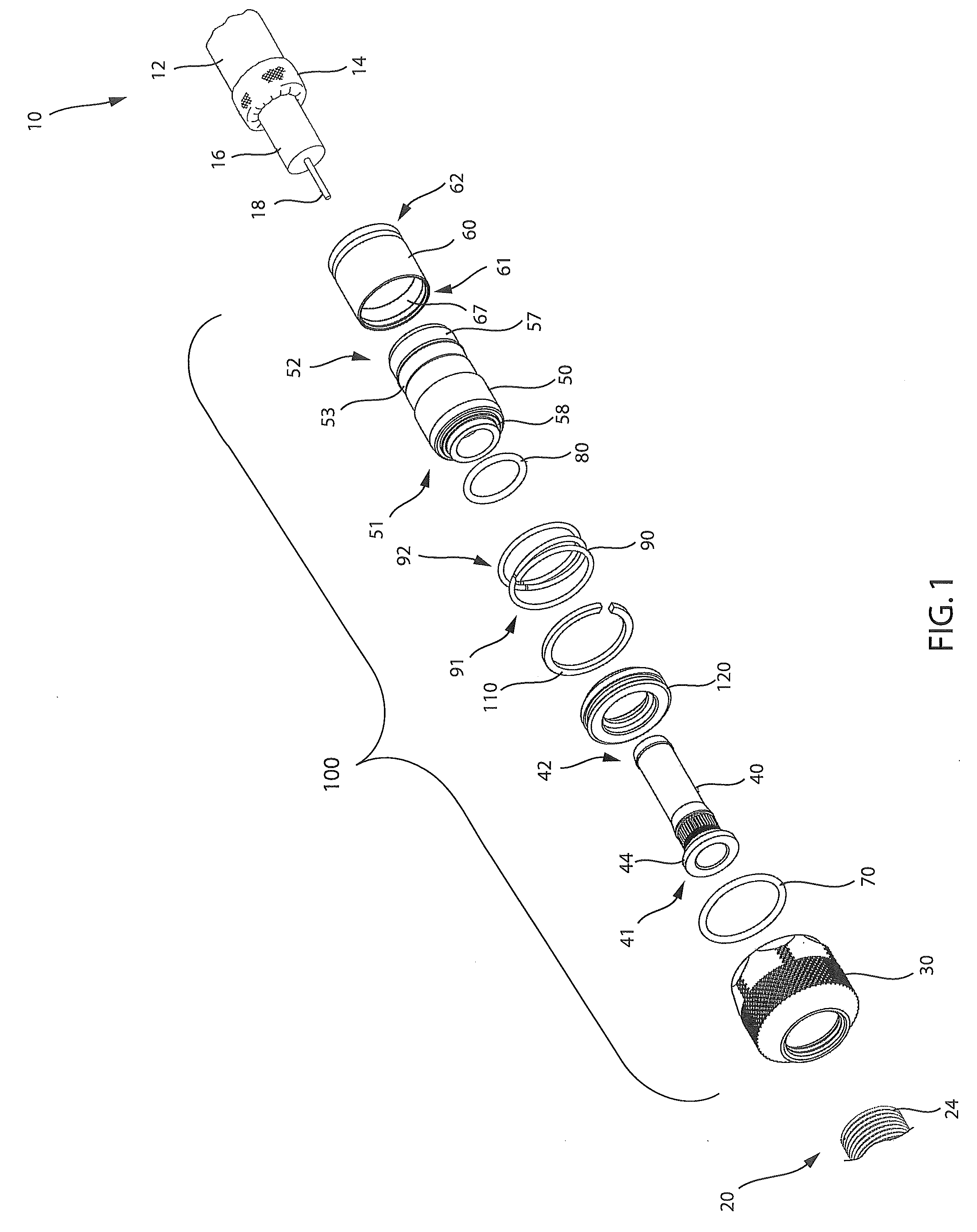
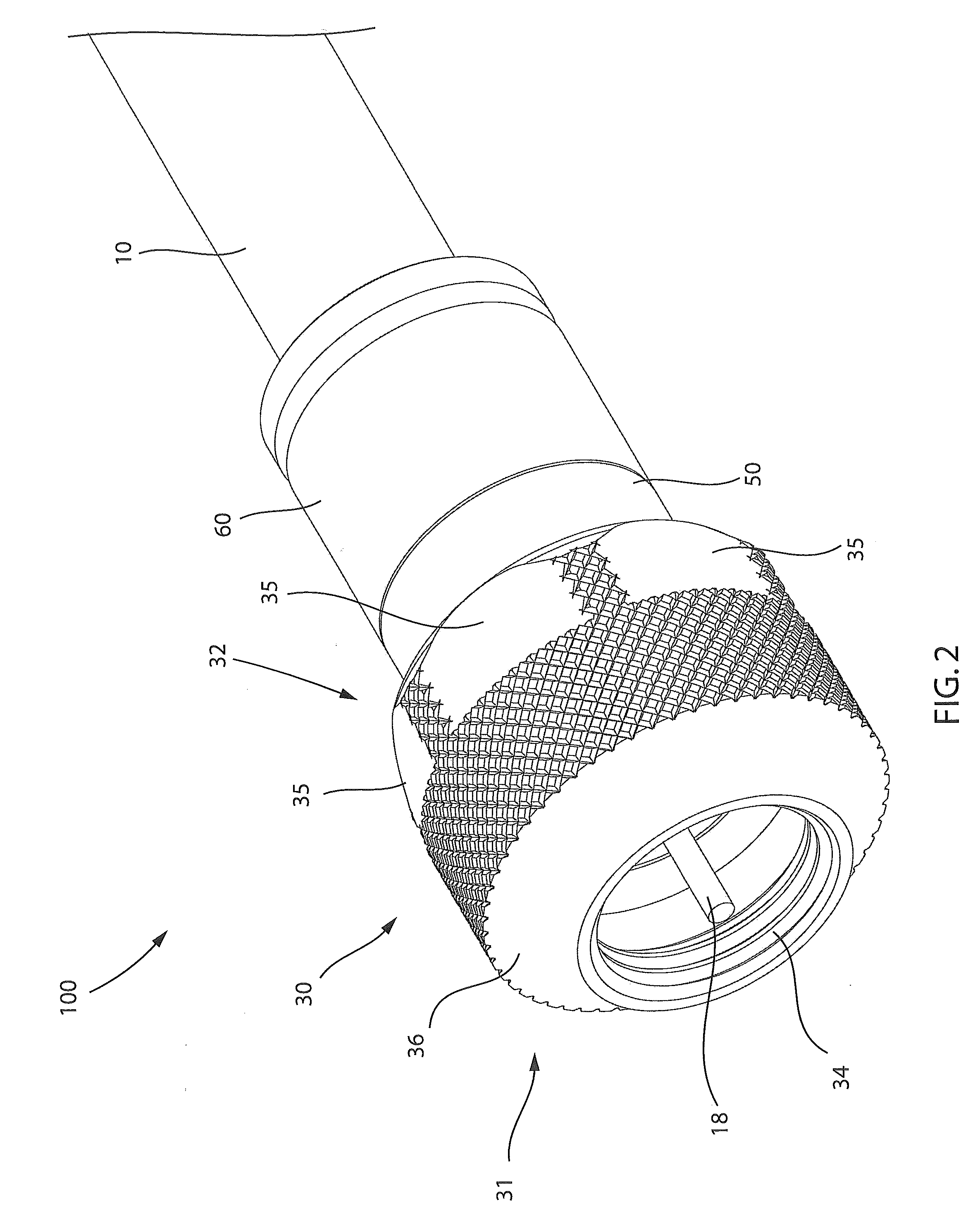
[0026]Referring to the drawings, FIG. 1 depicts one embodiment of a coaxial cable connector 100. The coaxial cable connector 100 may be operably affixed to a coaxial cable 10 having a protective outer jacket 12, a conductive grounding shield 14, an interior dielectr...


PUM


Abstract

An F-type connector for connecting a coaxial cable to an interface port and extending an RF shield therebetween is provided. The connector includes a connector body having a first end and a second end, a post, attached to the connector body, a threaded nut, rotatable with respect to the post and also axially movable with respect to the connector body between a first position and a second position, a biasing member, operable to move the nut, and a joint stop element, located to interact with the biasing member and introduce obstructive structure that impedes axial movement of the nut.

Description

CROSS-REFERENCE TO RELATED APPLICATIONS[0001]This application claims the priority benefit of U.S. Provisional Patent Application No. 61 / 165,508 filed Apr. 1, 2009, and entitled COAXIAL CABLE CONNECTOR WITH IMPROVED PHYSICAL AND RFI SEALING.FIELD OF THE INVENTION[0002]The present invention relates to F-type connectors used in coaxial cable communication applications, and more specifically to connector structure sealing against ingress of physical environmental contaminants and providing improved torque engagement of the RF seal of such connectors against standard coaxial cable connector interface ports.BACKGROUND OF THE INVENTION[0003]Broadband communications have become an increasingly prevalent form of electromagnetic information exchange and coaxial cables are common conduits for transmission of broadband communications. Connectors for coaxial cables are typically connected onto complementary interface ports to electrically integrate coaxial cables to various electronic devices an...

Claims


Application Information

Patent Timeline
Patent Type & Authority Applications(United States)
IPC IPC(8): H01R9/05
CPCH01R9/0521H01R13/622H01R13/6593H01R2103/00
Inventor PURDY, ERICPALINKAS, RAYMOND
Owner PPC BROADBAND INC
Why Eureka
Try Eureka