Buck-mode boost converter with regulated output current

Active Publication Date: 2010-10-14
ANALOG DEVICES INT UNLTD
View PDF8 Cites 4 Cited by
  • Summary
  • Abstract
  • Description
  • Claims
  • Application Information

AI Technical Summary

Benefits of technology

[0010]The buck-mode boost controller may be configured to control the electronic power switch and to turn the electronic power switch off each time the average current through the

Problems solved by technology

The number of connection pins to the monolithic package may be limited by its size and governing standards.
The number of LED channels which the monolithic package can control may therefore be limited by the number of required connections to each LED channel.

Method used


Image

  • Buck-mode boost converter with regulated output current
  • Buck-mode boost converter with regulated output current
  • Buck-mode boost converter with regulated output current

Examples


Embodiment Construction

[0023]Illustrative embodiments are now discussed. Other embodiments may be used in addition or instead. Details that may be apparent or unnecessary may be omitted to save space or for a more effective presentation. Conversely, some embodiments may be practiced without all of the details that are disclosed.

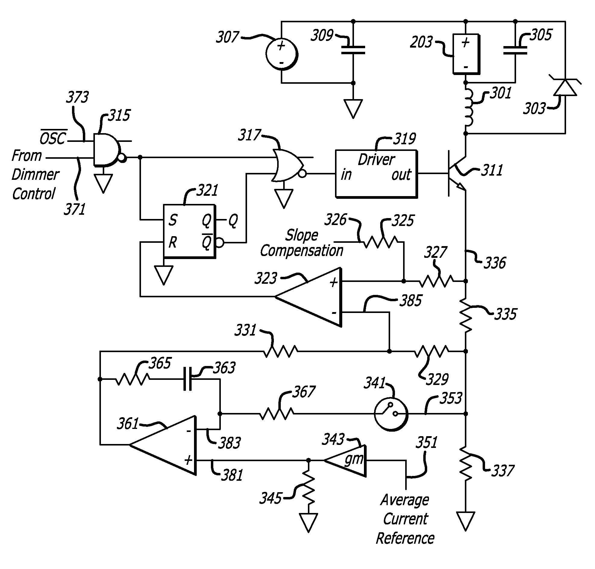
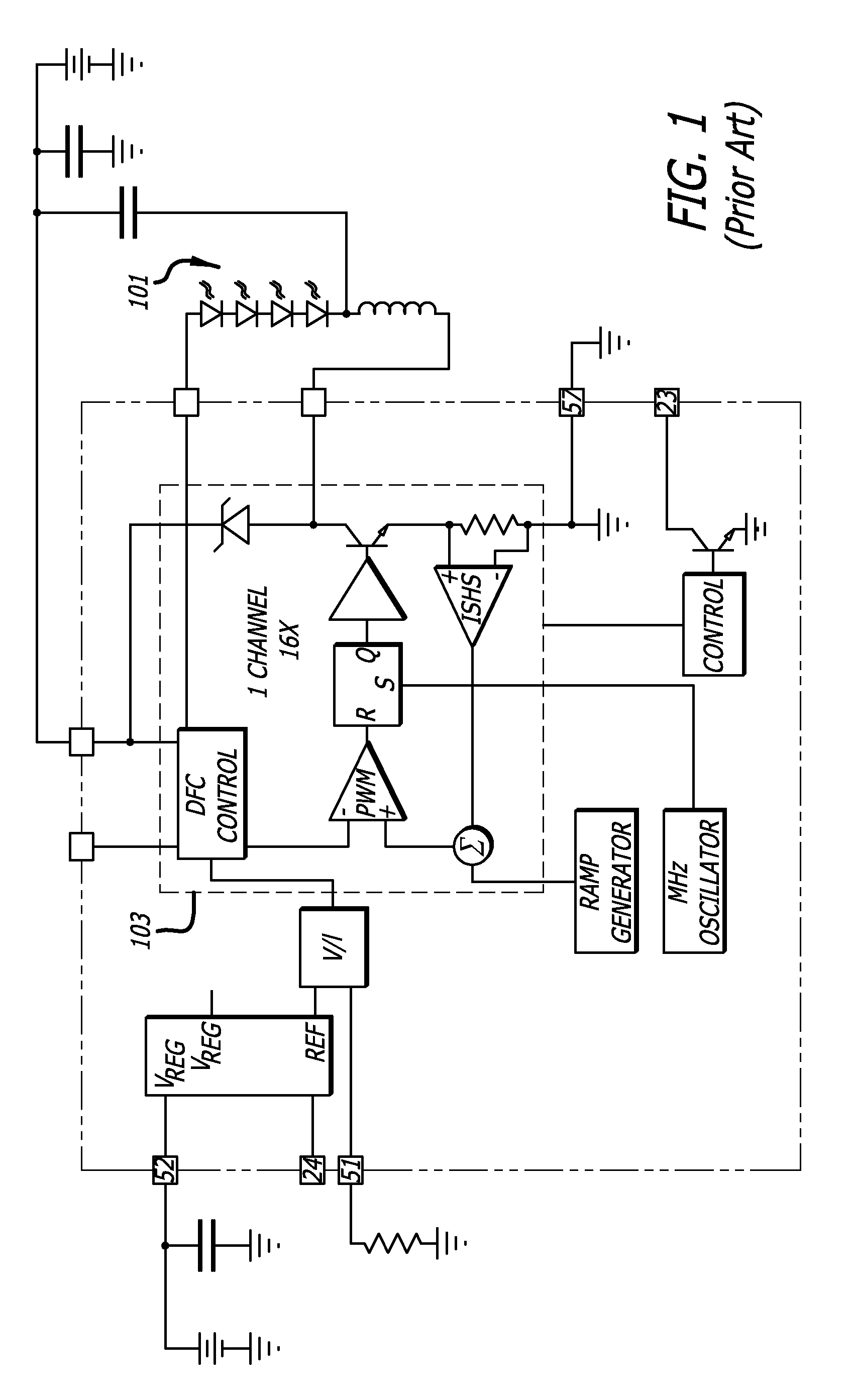
[0024]FIG. 1 is a diagram of a prior art LED driver circuit that includes a buck-mode boost converter that provides a regulated output current and that requires two connections to each channel of LEDs.

[0025]As illustrated in FIG. 1, a single channel of LEDs 101 may be connected to a buck-mode boost circuit which, in turn, is driven by a buck-mode boost converter. Details about the operation of this circuit are set forth in the Linear Technology Data Sheet on its 16 Channel Buck Mode LED Driver (part number LT3595) (Document No. LT 0807) (2007), the entire contents of which is incorporated herein by reference.

[0026]As indicated in FIG. 1, only one channel of control circuitry is sho...


PUM


Abstract

An LED driver circuit that includes a buck-mode boost converter that provides a regulated output current and that requires only a single connection to each channel of LEDs. The buck-mode boost controller may include a current regulator that includes an integrator. The current regulator may be configured to integrate a difference between a reference signal that is representative of the desired level of the average current through the electronic power switch and a detected signal that is representative of the actual current that is being delivered to the buck-mode boost circuit through the electronic power switch. The reference signal to the integrator may not change during operation of the buck-mode converter. The current regulator may be configured to deactivate the integrator and / or to disconnect the detected signal from the integrator while the electronic power switch is off.

Description

BACKGROUND[0001]1. Technical Field[0002]This disclosure relates to power switching converters and to LED driver circuits.[0003]2. Description of Related Art[0004]Various loads may be driven with a regulated current. LED lights, for example, may be illuminated by driving them with a regulated current. This regulated current may be provided by a power switching converter which converts a setting of a control into a proportional driving current, such as a dimmer or other type of control.[0005]A buck-mode boost converter may be used as the power switching converter. Two or more connections between each channel of LEDs and the buck-mode boost converter may be required in order for the converter to detect the amount of current in LEDs and, in turn, to accurately regulate this current.[0006]A single monolithic package may be used to separately control the current that is delivered to several channels of LEDs. The number of connection pins to the monolithic package may be limited by its siz...

Claims


Application Information

Patent Timeline
IPC IPC(8): H05B37/02H05B44/00
CPCH02M3/156Y02B20/347H05B33/0818H02M2001/0009Y02B20/30H05B45/3725H02M1/0009
Inventor NEGRETE, MICHAEL GEORGE
Owner ANALOG DEVICES INT UNLTD
Why Eureka
Try Eureka