Dimmable LED luminaire

a led luminaire and led light source technology, applied in the direction of cathode-ray/electron beam tube circuit elements, light source semiconductor devices, lighting and heating apparatus, etc., can solve the problems of affecting the installation of led luminaires into existing lighting systems, affecting the useful life of conventional light sources, and generating undesirable heat sources

Inactive Publication Date: 2010-11-04
LIGHTING SCI GROUP
View PDF8 Cites 118 Cited by
  • Summary
  • Abstract
  • Description
  • Claims
  • Application Information

AI Technical Summary

Benefits of technology

[0011]An embodiment of the invention includes a luminaire having a base, a power supply, a middle member, and a frosted bulb. The base includes an electrical connector thereon, wherein the electrical connector is sized and shaped to be received in an Edison medium socket. The power supply is arranged within the base, the power supply being electrically coupled to the electrical connector. The middle member is coupled to the base, the middle member including: a shell member having a hollow inner portion and a first surface on one end, wherein a first wall is arranged adjacent the base; a cup member disposed within the hollow inner portion, the cup member having a second wall arranged opposite said first wall; a heat sink disposed about the cup member within the shell me

Problems solved by technology

Conventional light sources, such as incandescent light bulbs for example, typically have a short useful life.
Typically, these power sources generate an undesirable amount of heat.
While this arrangement solves the issue

Method used


Image

  • Dimmable LED luminaire
  • Dimmable LED luminaire
  • Dimmable LED luminaire

Examples


Embodiment Construction

[0040]Although the following detailed description contains many specifics for the purposes of illustration, anyone of ordinary skill in the art will appreciate that many variations and alterations to the following details are within the scope of the invention. Accordingly, the following preferred embodiments of the invention are set forth without any loss of generality to, and without imposing limitations upon, the claimed invention.

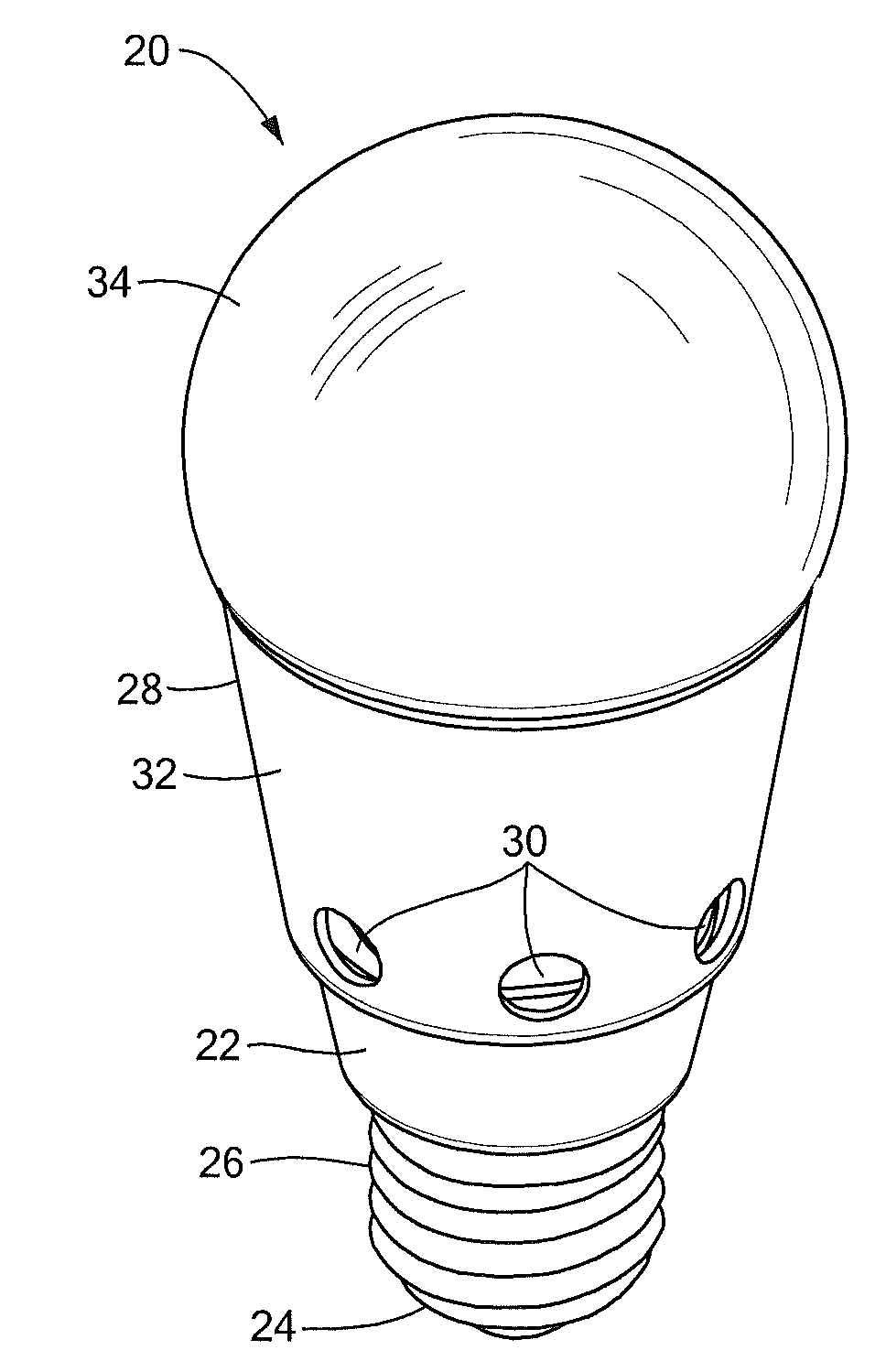
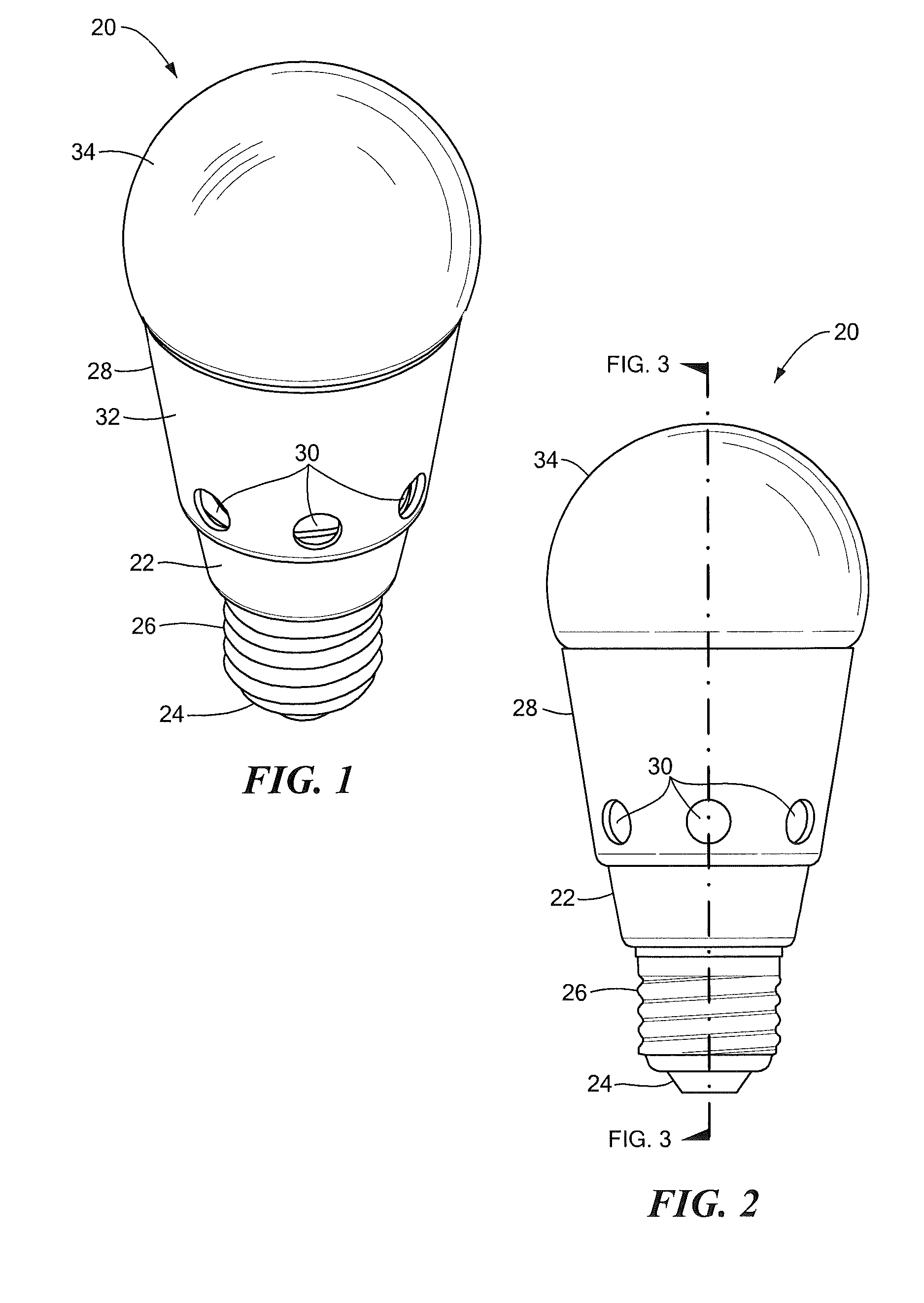
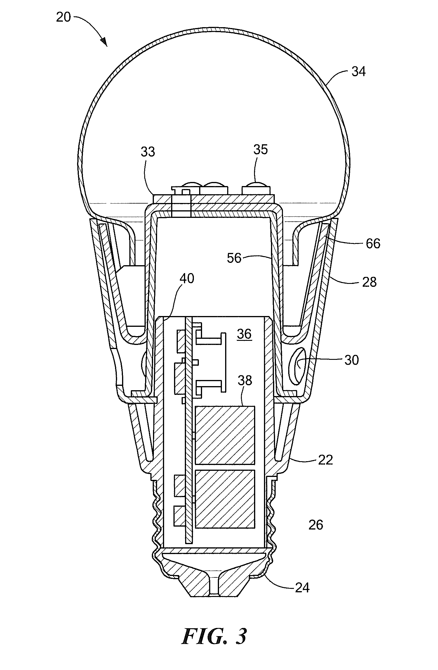
[0041]An embodiment of the invention, as shown and described by the various figures and accompanying text, provides a luminaire with light emitting diodes (LEDs) that is suitable for replacing a standard A19 light bulb, such as that defined by ANSI C78.20-2003 for example, equipped with a threaded connector, sized and shaped as an Edison E26 medium base defined by ANSI C81.61-2007 or IEC standard 60061-1 (7004-21A-2) for example, suitable to be received in a standard electric light socket, where the driver circuit for the luminaire is self-contained with...


PUM

PropertyMeasurementUnit
Currentaaaaaaaaaa
Electric potential / voltageaaaaaaaaaa
Noiseaaaaaaaaaa

Abstract

A luminaire includes an Edison type electrical base, an optic, and a heat sink disposed between the base and the optic. An LED driver circuit is disposed at least partially within the heat sink, and is disposed in electrical communication with the base. An LED assembly is disposed in thermal communication with a surface of the heat sink, and in electrical communication with the driver circuit, the LED assembly includes an LED. The driver circuit includes circuitry that converts an AC signal at the base to a DC signal and provides the DC signal to the LED assembly, the circuitry includes holding current circuitry that produces a holding current for an electrical dimmer disposed upstream of the base in response to a current to the LED assembly being reduced for light dimming purposes.

Description

CROSS REFERENCE TO RELATED APPLICATIONS[0001]This application claims the benefit of U.S. Provisional Application Ser. No. 61 / 174,268, filed Apr. 30, 2009, which is incorporated herein by reference in its entirety.BACKGROUND OF THE INVENTION[0002]The subject matter disclosed herein relates generally to a luminaire having an LED light source, particularly to an LED luminaire sized to replace an incandescent light bulb, and more particularly to an LED luminaire sized to replace an A19 incandescent light bulb.[0003]In recent years, there has been an increased interest in luminaires, sometimes referred to as “light bulbs” or lamps, which use light emitting diodes (“LEDs”) as a light source. These luminaires are quite attractive since they overcome many of the disadvantages of the conventional light sources, which include incandescent light bulbs, fluorescent light bulbs, halogen light bulbs and metal halide light bulbs.[0004]Conventional light sources, such as incandescent light bulbs fo...

Claims


Application Information

Patent Timeline
IPC IPC(8): H01K1/62
CPCF21V3/00F21Y2101/02H05B33/0803H05B33/0809H05B33/0815F21V29/83F21V29/004F21K9/1355F21V23/006F21V29/74H05B33/0845F21K9/23F21Y2115/10F21K9/238F21V3/02F21V3/062F21V3/061H05B45/10H05B45/37H05B45/3575H05B45/36H05B45/355
Inventor MAXIK, FREDRIC S.HENDERSON, DAVIDWIDJAJA, ADDY S.
Owner LIGHTING SCI GROUP
Why Eureka
Try Eureka