Configurable LED driver/dimmer for solid state lighting applications

a technology of led driver and driver, which is applied in the direction of electric variable regulation, process and machine control, instruments, etc., can solve the problems that lighting companies are faced with considerable challenges in adopting ssl technology, and achieve the effects of reducing power consumption, improving efficiency, and reducing no load power consumption

Active Publication Date: 2011-08-25
MATE
View PDF9 Cites 127 Cited by
  • Summary
  • Abstract
  • Description
  • Claims
  • Application Information

AI Technical Summary

Benefits of technology

[0013]In another aspect of the present disclosure, the power source includes a digital controller to decrease power consumption of a relay coil as part of an inrush current limit circuit to reduce power consumption and improve efficiency.
[0014]In another aspect of the present disclosure, the power source utilizes an independent efficient auxiliary power source and one or more digital controllers to provide power to the communication interface. A digital controller disables various electrical circuits during black out lighting conditions to reduce no load power consumption and improve efficiency.

Problems solved by technology

However, lighting companies are faced with considerable challenges in adopting SSL technology due to their unfamiliarity and lack of expertise in the driving and dimming requirements for LEDs.

Method used


Image

  • Configurable LED driver/dimmer for solid state lighting applications
  • Configurable LED driver/dimmer for solid state lighting applications
  • Configurable LED driver/dimmer for solid state lighting applications

Examples


Embodiment Construction

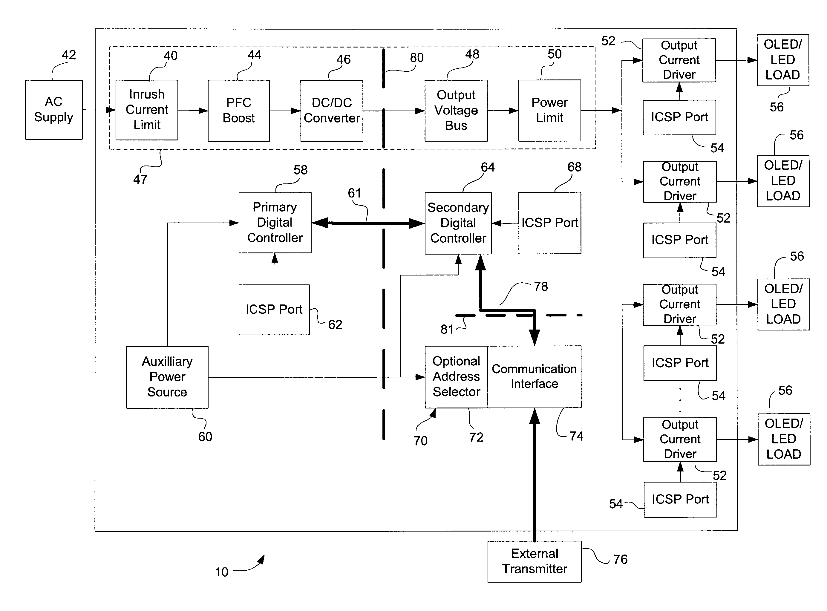
[0028]In general, the present disclosure is directed at a method and apparatus for providing a configurable LED Driver / dimmer. In the current description, the Driver / dimmer will be referred to as a dimmer, however, it will be understood that the configurable apparatus can function as either a driver, a dimmer or both. In the preferred embodiment, the dimmer is used for Solid State Lighting (SSL) applications.

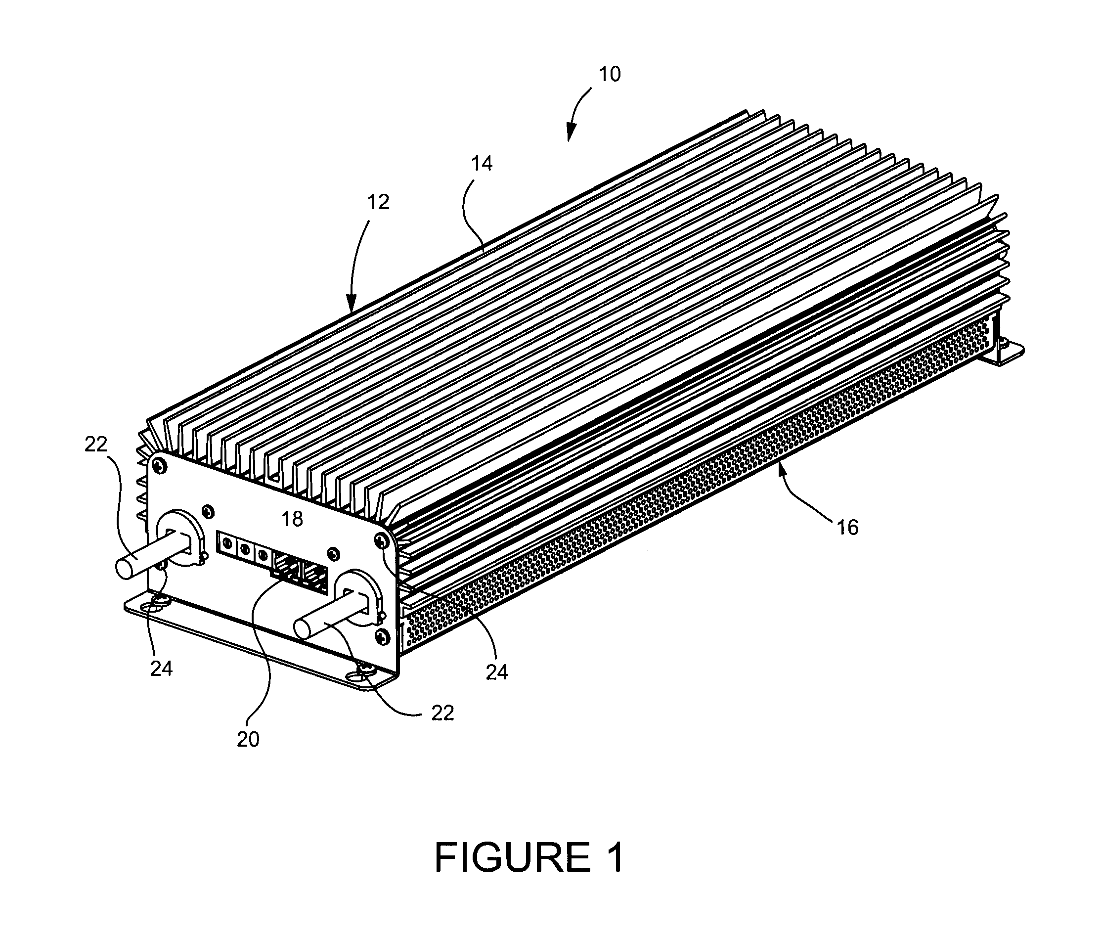
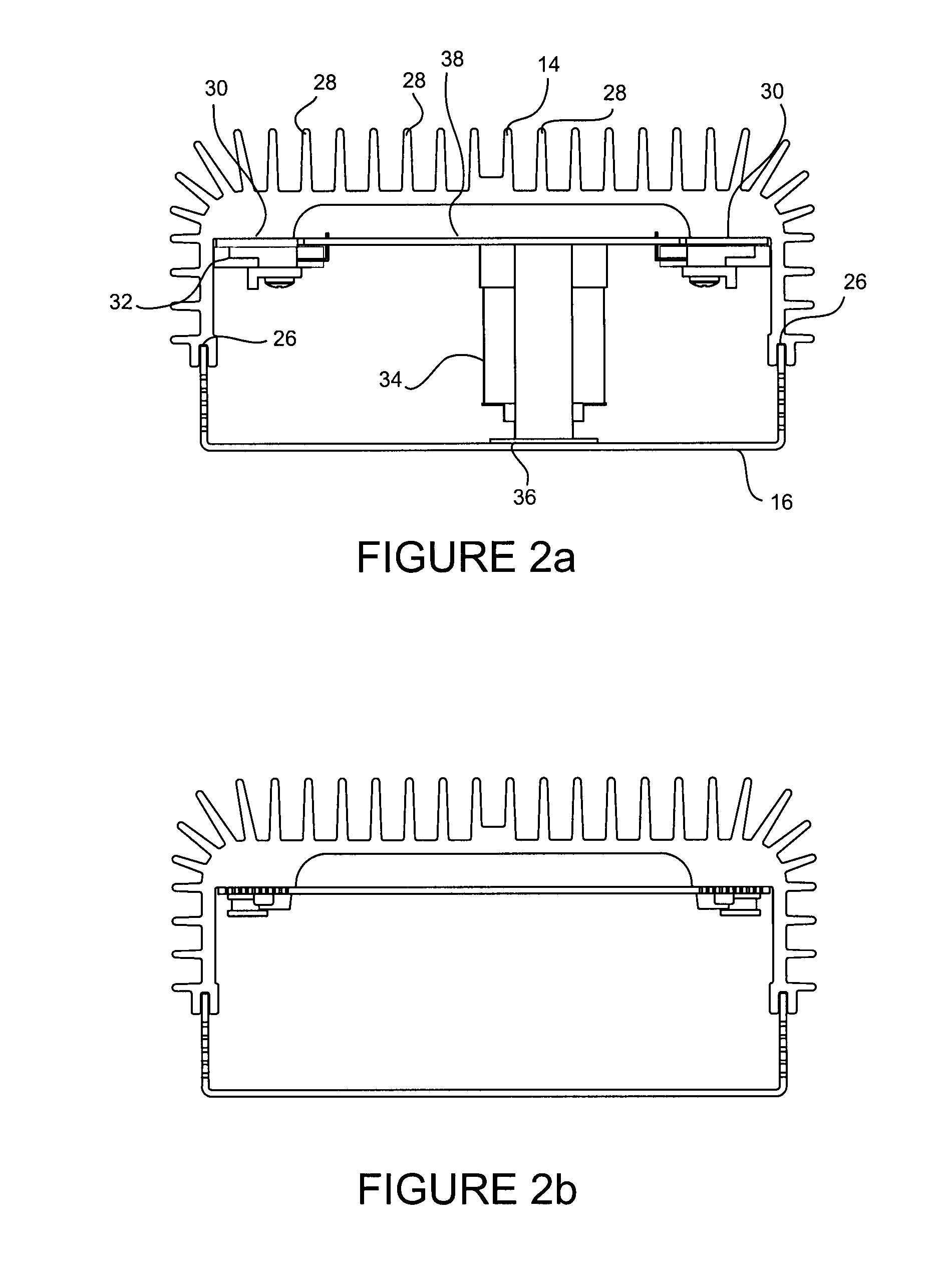
[0029]Turning to FIG. 1, a perspective view of an LED dimmer is shown. The LED dimmer 10 includes a body portion 12, or housing, which includes a monolithic aluminum heatsink 14 and a U-shaped chassis 16. Cross-sectional views of the dimmer 10 are provided in FIGS. 2a and 2b.

[0030]The dimmer 10 further includes a front plate 18 which includes a plurality of ports 20 along with a set of conductor cables 22. The front plate 18 is fastened to the body portion 12 via a set of fasteners 24, such as screws. In this embodiment, as conductor cables are used to provide output power to L...


PUM


Abstract

The disclosure is directed at a configurable light emitting diode (LED) driver/dimmer for controlling a set of light fixture loads comprising: a power circuit; a primary digital controller for controlling the power circuit; a set of output current drivers, each of the set of output current drivers connected to one of the set of light fixture loads for controlling the associated light fixture load; a secondary digital controller for controlling the set of output current drivers; wherein the secondary controller transmits LED control information to control outputs of the set of output current drivers; and wherein the secondary digital controller provides digital feedback control information to the primary digital controller.

Description

CROSS-REFERENCE TO RELATED APPLICATIONS[0001]This application claims the benefit of U.S. Provisional Application No. 61 / 097,063 Sep. 18, 2008, which is incorporated herein by reference.BACKGROUND OF THE DISCLOSURE[0002]With the rapid increase in light emitting diode (LED) efficacies for high powered LEDs, the latest technologies have exceeded incandescent and halogen sources and are now starting to compete with fluorescent, mercury vapour, metal halide and sodium lighting. In addition to better energy usage, LEDs also have considerable advantages over traditional light sources such as long life, better durability and improved color generating abilities. The advancement of LED technology by various manufacturers has produced high power LEDs with various recommended drive currents such as 350 mA, 500 mA, 700 mA, 1000 mA, and 1400 mA or higher.[0003]In recent years, controllable power sources for Solid State Lighting (SSL) applications have entered the market with integrated features. ...

Claims


Application Information

Patent Timeline
Patent Type & Authority Applications(United States)
IPC IPC(8): H05B37/02H05K7/20H05B44/00
CPCH05B33/0815H05B33/0896H05B33/0806H05B45/37H05B45/375H05B45/30H05B45/355H05B45/38H05B45/10H05B45/385H05B45/46H05B45/00H05B47/18H05B45/60
Inventor TIKKANEN, DAVIDNEUDORF, JASONLYONS, STEVENSCOTT, TODD WILLIAMHATHAWAY, KYLE GRAHAMEJANSEN, DAVID WAINESWORTH
Owner MATE
Why Eureka
Try Eureka