Medical manipulator and medical robot system

a robot system and manipulator technology, applied in the field of medical manipulators and medical robot systems, can solve the problems of presenting itself as an obstacle in the operative field, and it is difficult to provide a wide operative field in the body cavity

Inactive Publication Date: 2010-10-14
TERUMO KK
View PDF6 Cites 99 Cited by
  • Summary
  • Abstract
  • Description
  • Claims
  • Application Information

AI Technical Summary

Benefits of technology

[0013]It is an object of the present invention to provide a medical manipulator which is capable of keeping

Problems solved by technology

The body cavity may contain various organs in addition to the organ as the affected region, which make it difficult to provide a wide operative field in the body cavity.
However,

Method used


Image

  • Medical manipulator and medical robot system
  • Medical manipulator and medical robot system
  • Medical manipulator and medical robot system

Examples


first embodiment

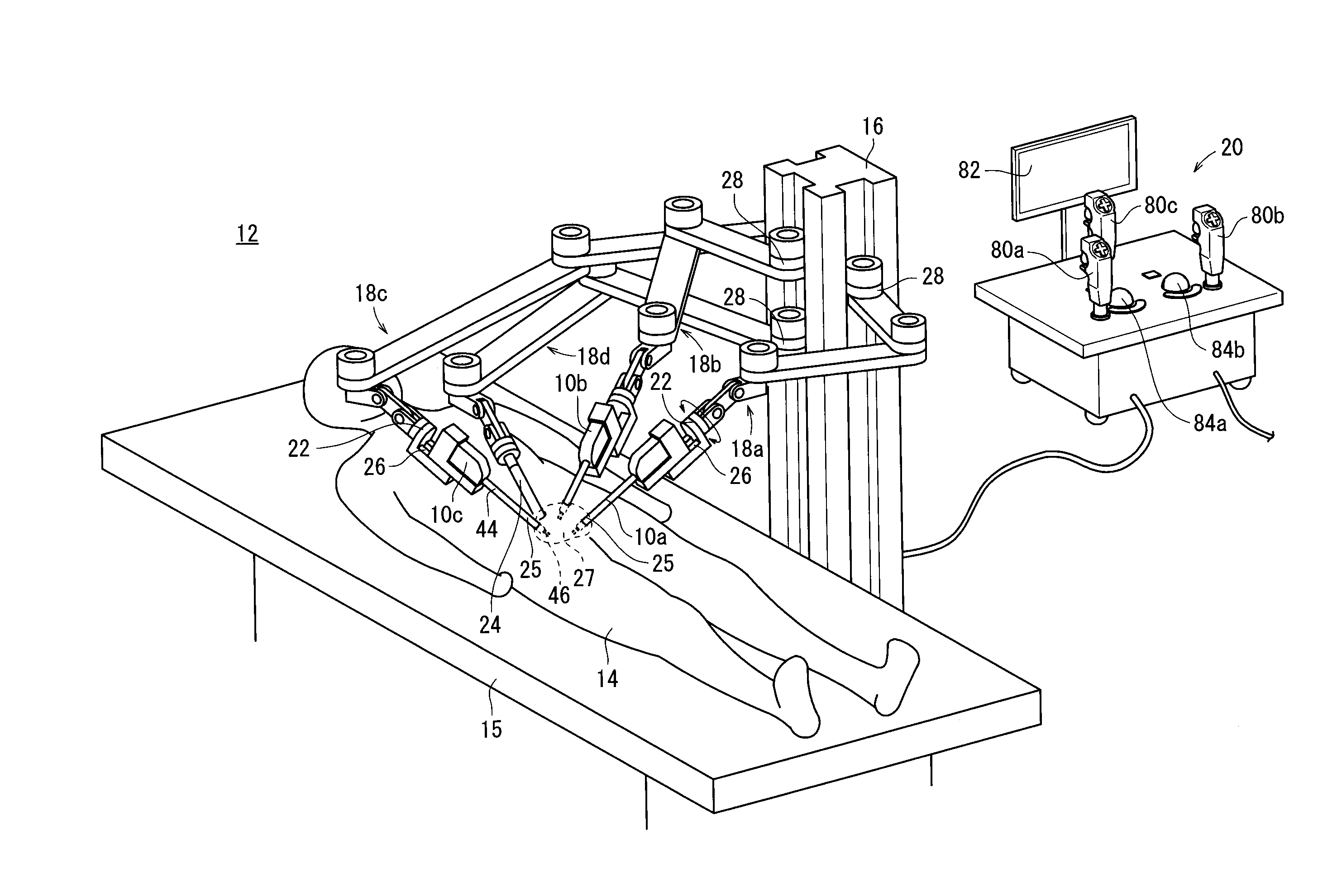
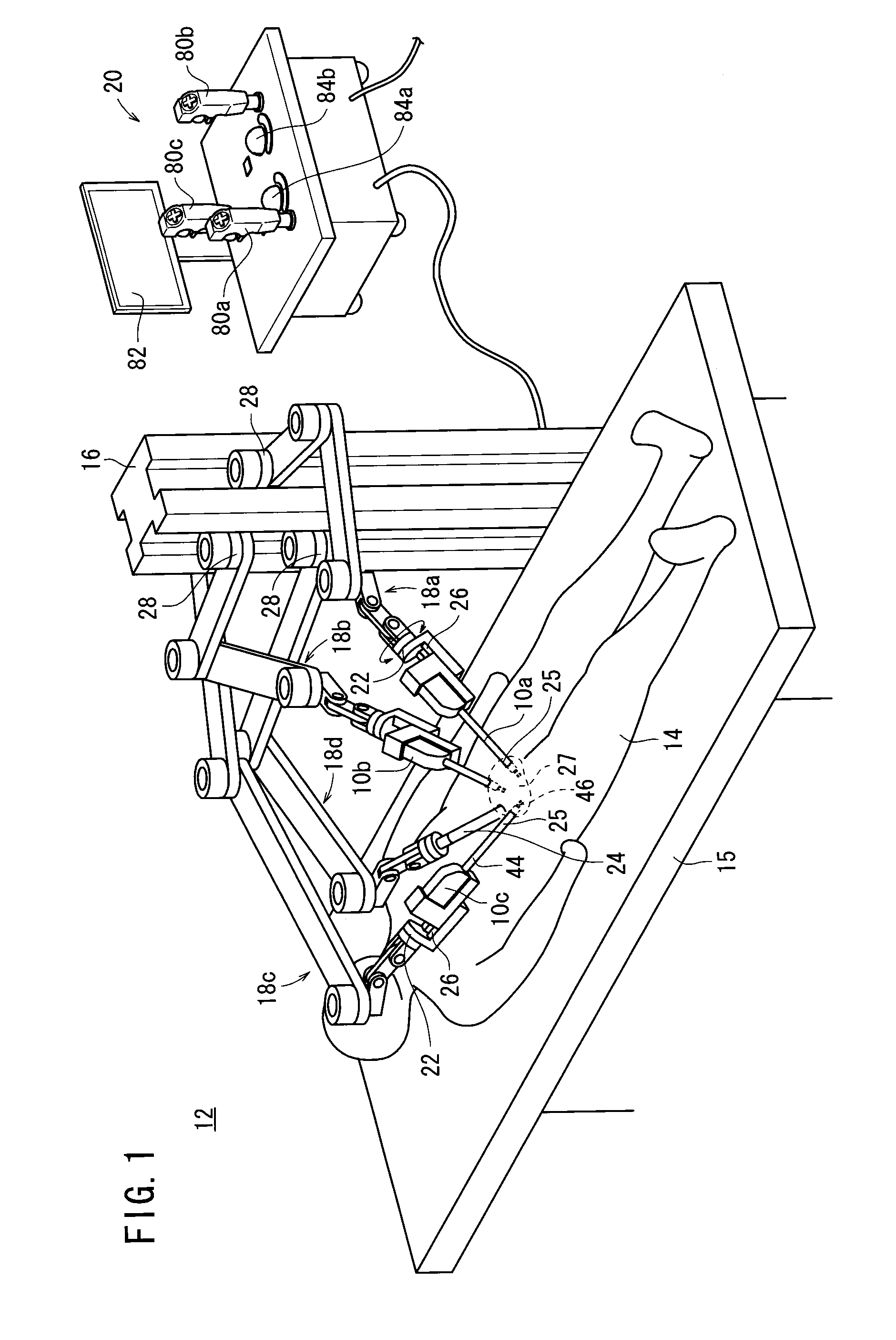
[0056]As shown in FIG. 1, a medical manipulator 10c and a medical robot system 12 according to the present invention are particularly suitable for performing a laparoscopic surgical operation on a patient 14.

[0057]The medical robot system 12 comprises a station 16 disposed near a surgical bed 15, four robot arms 18a, 18b, 18c, 18d mounted on the station 16, and a console (controller) 20 for controlling the medical robot system 12 in its entirety. The robot arm 18c will also be referred to as a first robot arm, and the robot arm 18d as a second robot arm. The robot arms 18a through 18d and the console 20 may be connected to each other by a communication means comprising a wired link, a wireless link, a network, or a combination thereof. The console 20 is not required to control the medical robot system 12 in its entirety, but the robot arms 18a through 18d may be feedback-controlled by internal controllers combined with the medical robot system 12. The robot arms 18a through 18c may ...

second embodiment

[0128]FIG. 19 is a schematic view illustrative of a medical robot system according to the present invention. FIG. 19 shows manipulators 10d, 10e and an endoscope 24, which are constituent elements of the medical robot system.

[0129]The medical robot system according to the second embodiment differs from the medical robot system 10 according to the first embodiment in that the manipulator 10d having a different structure from the manipulator 10a is provided at the distal end of the robot arm 18a and the manipulator 10e having a different structure from the manipulator 10b is provided at the distal end of the robot arm 18b.

[0130]A rod-shaped member 44d of the manipulator 10d has an intermediate joint 60d in an intermediate portion thereof, and a rod-shaped member 44e of the manipulator 10e has an intermediate joint 60e in an intermediate portion thereof. The intermediate joints 60d, 60e have the same structure as the first intermediate joint 58 shown in FIGS. 2 and 4. More specificall...

third embodiment

[0144]FIG. 20 is a schematic view illustrative of a medical robot system according to the present invention. FIG. 20 shows manipulators 10c, 10d and an endoscope 24, which are constituent elements of the medical robot system.

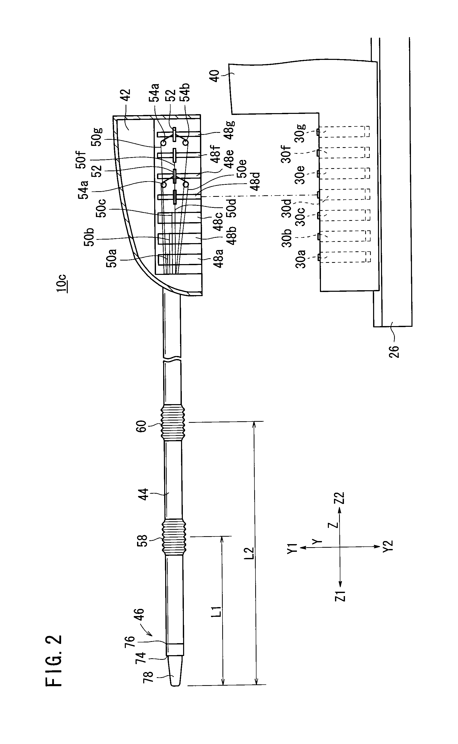
[0145]The medical robot system according to the third embodiment is a medical robot system in which the manipulator 10c (see FIG. 2) of the medical robot according to the first embodiment, instead of the manipulator 10e, is applied to the medical robot system according to the second embodiment. The manipulator 10d that is provided at the distal end of the robot arm 18a has the same structure as the manipulator 10d according to the second embodiment.

[0146]As described above, the manipulator 10c has the first intermediate joint 58 and the second intermediate joint 60, and accordingly the rod-shaped member 44 can be bent at two points. Thus, the manipulator 10c has greater flexibility to its possible shape, compared to the manipulator 10e (see FIG. 19). The trocar ...


PUM


Abstract

The present invention relates to a medical manipulator and a medical robot system. The manipulator has a connecting block, a joint shaft, and a distal-end working unit. The distal-end working unit has a gripper, a pitch axis, and a yaw axis which serve as distal-end joints for changing the orientation of the gripper. The gripper, the pitch axis, and the yaw axis are operated by rotors around which wires are wound. The joint shaft has a first intermediate joint and a second intermediate joint which are bendable by the wires which are moved back and forth. Since the manipulator can be bent at the first intermediate joint and the second intermediate joint, the joint shaft can appropriately be placed, and the gripper can be adjusted to an appropriate orientation with respect to an organ by being turned around the pitch axis and the yaw axis.

Description

CROSS-REFERENCE TO RELATED APPLICATIONS[0001]This application is a continuation-in-part and claims the benefit of priority from U.S. application Ser. No. 12 / 327,189 filed Dec. 3, 2008, the entire contents of which are hereby incorporated by reference. U.S. application Ser. No. 12 / 327,189, claims the benefit of Priority to Japanese Patent Application No. 2007-339211, filed on Dec. 28, 2007.BACKGROUND OF THE INVENTION[0002]1. Field of the Invention[0003]The present invention relates to a medical manipulator having a distal-end joint operable by flexible members that are actuated by actuators, and a medical robot system for actuating such a medical manipulator with a robot arm.[0004]2. Description of the Related Art[0005]According to a laparoscopic surgical operation process, small holes are opened in the abdominal region, for example, of a patient, and an endoscope and manipulators or forceps are inserted into such holes. The surgeon performs a surgical operation on the patient with t...

Claims


Application Information

Patent Timeline
IPC IPC(8): A61B19/00
CPCA61B19/2203A61B19/5212A61B2017/2908A61B19/22A61B2019/2242A61B2019/2276A61B1/00149A61B2019/2223A61B2034/742A61B34/70A61B34/71A61B90/361A61B34/30A61B34/37
Inventor OMORI, SHIGERU
Owner TERUMO KK
Why Eureka
Try Eureka