Shutter Panel Having Louvers Aligned Along a Single Plane

a technology of louvers and shutters, applied in the field of shutter panels, can solve the problem of relatively ungainly appearance of shutters, and achieve the effect of attractive design and encouraging movemen

Active Publication Date: 2010-10-21
MACIULEWICZ PETER SCOTT
View PDF15 Cites 11 Cited by
  • Summary
  • Abstract
  • Description
  • Claims
  • Application Information

AI Technical Summary

Benefits of technology

[0007]It is therefore a principal object and advantage of the present invention to provide a shutter having louvers aligned along a single plane.
[0008]It is an additional object and advantage of the present invention to provide a shutter having louvers that present a smooth surface when placed in the closed position.
[0009]It is a further object and advantage of the present invention to provide a shutter having louvers that may be provided with an attractive design.
[0010]In accordance with the foregoing objects and advantages, the present invention provides a shutter panel having a plurality of louvers may be closed into a uniform plane without any overlapping of edges, thereby providing an aesthetically pleasing design. Each louver of shutter panel a first post interconnected thereto for providing a pivot point and a second post positioned off-center with respect to first post for providing a motive force. The second posts of each louver are interconnected to each other by one or more control rods positioned with a cavity formed in the vertically extending stiles of the shutter panel. When any louver is pivoted, the control rod transmits the force to each other louver for movement in unison. Each louver is beveled to encourage movement between the open and closed positions and assist in the formation of a substantially flat surface when the shutter is closed.BRIEF DESCRIPTION OF THE SEVERAL VIEWS OF THE DRAWING(S)
[0011]The present invention will be more fully understood and appreciated by reading the following Detailed Description in conjunction with the accompanying drawings, in which:
[0012]FIG. 1 is a perspective view of a shutter according to the present invention in the closed position.

Problems solved by technology

These shutters are relatively ungainly in appearance, however, due to the need for an external rod and the overlapping of the louvers when the shutter is in a closed position.

Method used


Image

  • Shutter Panel Having Louvers Aligned Along a Single Plane
  • Shutter Panel Having Louvers Aligned Along a Single Plane
  • Shutter Panel Having Louvers Aligned Along a Single Plane

Examples


Embodiment Construction

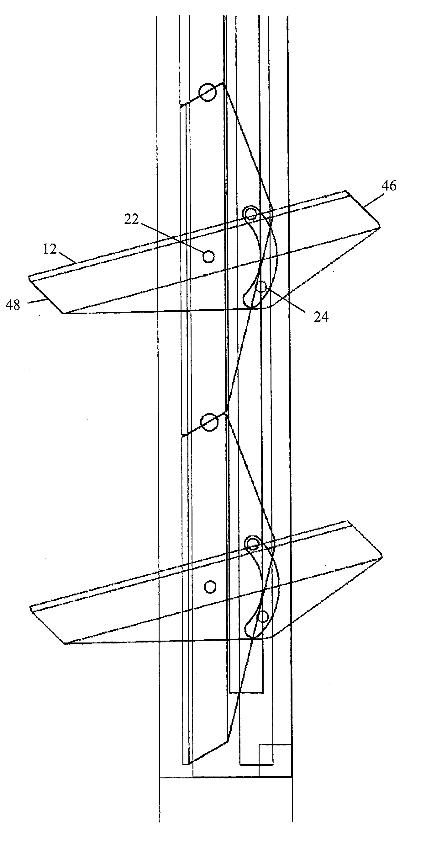
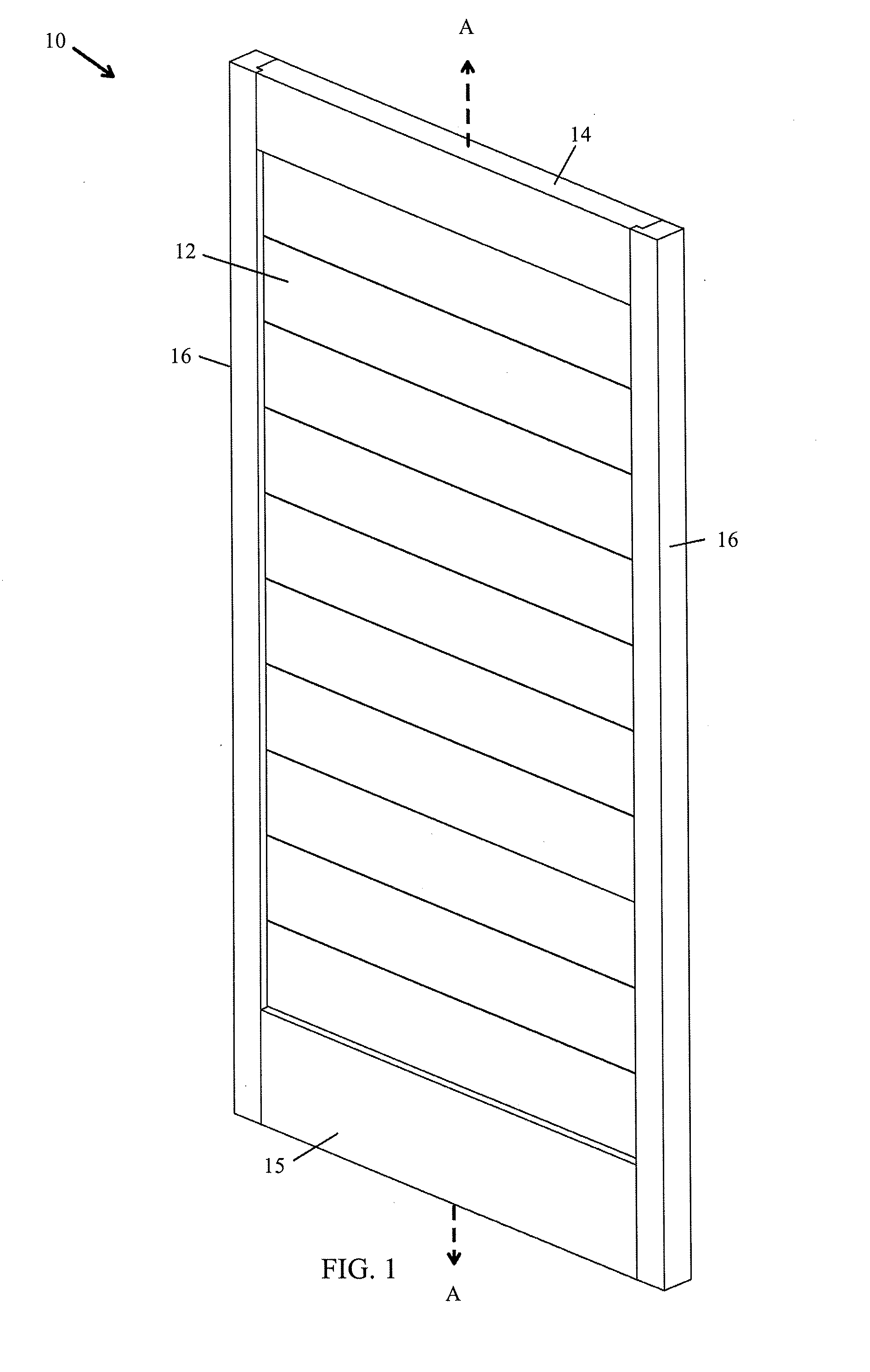
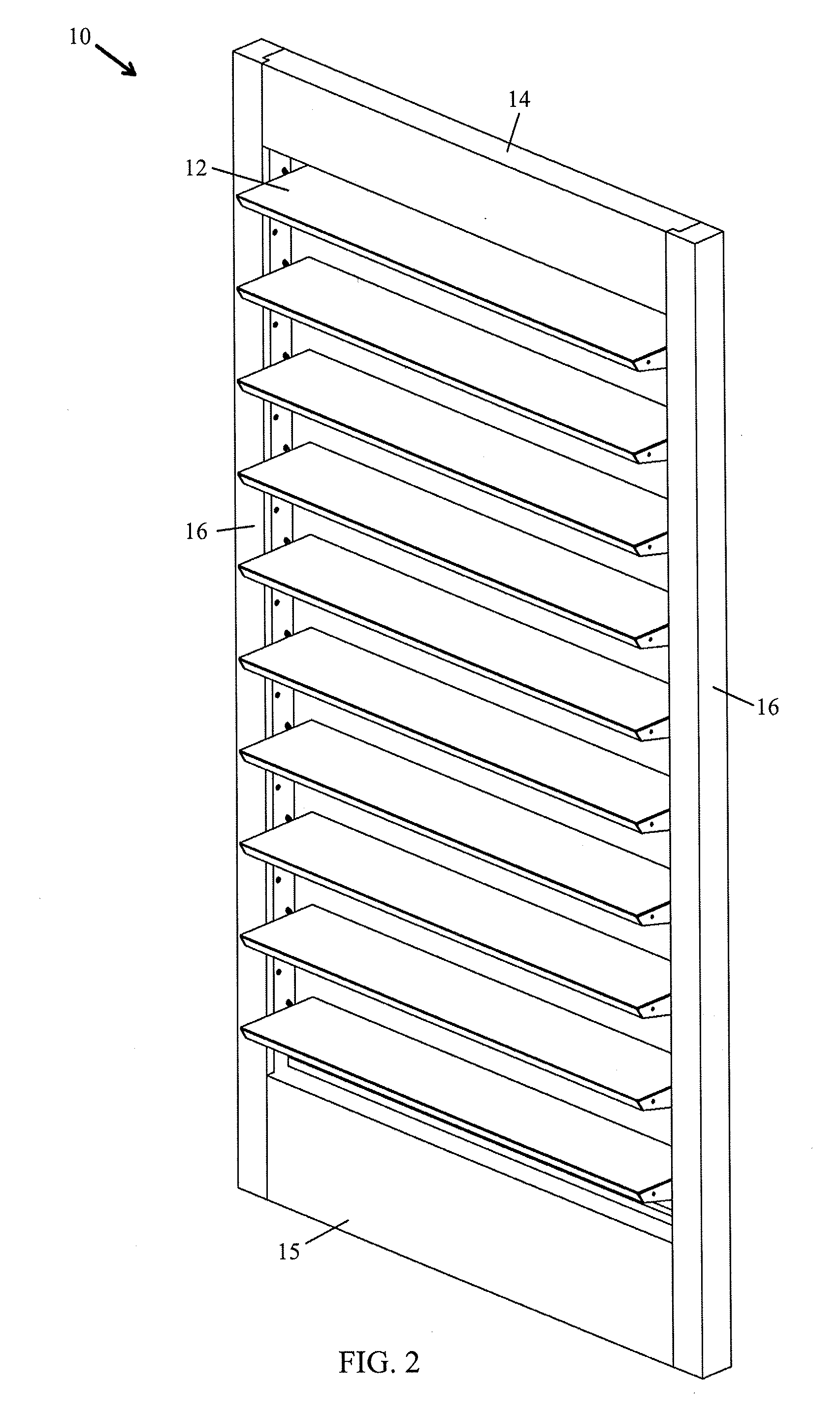
[0024]Referring now to the drawings, wherein like reference numerals refer to like parts throughout, there is seen in FIG. 1 a shutter 10 comprising a series of louvers 12 according to the present invention. Shutter 10 is in the closed position, where each louver 12 extends along a common plane A-A and presents a substantially flat surface without any overlapping of adjacent louvers 12 as with conventional designs. Shutter 10 further comprises a top rail 14 and a bottom rail 15, both of which extend horizontally between two, spaced apart vertical stiles 16. Similarly, louvers 12 also extend horizontally between stiles 16 and are attached thereto for pivotal movement, as will be described in detail herein. As seen in FIG. 2, louvers 12 may be pivoted to open shutter 10 to allow light to pass through. Noticeably absent from shutter 10 is any external rod for movement of the louvers 12, or any overlapping of adjacent louvers 12, as a result of the positioning one or two driving mechani...


PUM


Abstract

A shutter panel having multiple louvers that may be opened or closed in unison and which provide a flat, non-overlapping surface when placed in the closed position. Each louver is provided with a pivot post and a drive post, and the drive posts of each louver are interconnected to one or more control rods hidden within the stiles of the shutter panel. Each louver is beveled to encourage movement between the open and closed positions, and to assist with the formation of a substantially flat surface when the louvers are placed in the closed positions. The substantially flat surface formed when the louvers are closed may include an aesthetic design applied thereon or engraved therein.

Description

[0001]The present invention claimed priority to U.S. Provisional Application No. 61 / 169,463, filed Apr. 15, 2009.BACKGROUND OF THE INVENTION[0002]1. FIELD OF THE INVENTION[0003]The present invention relates to shutter panels and, more particularly, to a shutter panel that may be closed into a position where each of a plurality of louvers are coplanar and non-overlapping.[0004]2. DESCRIPTION OF THE RELATED ART[0005]Adjustable blinds and the like are often used in homes and commercial locations to reduce the amount of sunlight that enters a particular room through a window or other opening, or to provide privacy by obscuring the view through the window or opening. Conventional blinds comprise one or more panels, each of which includes a series of vertically or horizontally extending louvers or slats that may be moved between a open position, where the louvers are positioned in parallel with respect to each other, and a closed position, wherein each louver overlaps an adjacent louver t...

Claims


Application Information

Patent Timeline
Patent Type & Authority Applications(United States)
IPC IPC(8): E06B7/086
CPCE06B7/086
Inventor MACIULEWICZ, PETER SCOTT
Owner MACIULEWICZ PETER SCOTT
Why Eureka
Try Eureka