Automated Unwind System with Auto-Splice

Active Publication Date: 2010-10-21
C G BRETTING MFG
View PDF25 Cites 21 Cited by
  • Summary
  • Abstract
  • Description
  • Claims
  • Application Information

AI Technical Summary

Benefits of technology

[0055]An apparatus, according to the invention, may also include a coil drive arrangement for receiving the first and second coils and driving the coils in at least the unwind direction about

Problems solved by technology

Although forming the splice through a manual process generally is the simplest approach, and avoids the need for complicated automated splicing and roll handling equipment, manual splicing is often undesirable bec

Method used


Image

  • Automated Unwind System with Auto-Splice
  • Automated Unwind System with Auto-Splice
  • Automated Unwind System with Auto-Splice

Examples


exemplary embodiment 100

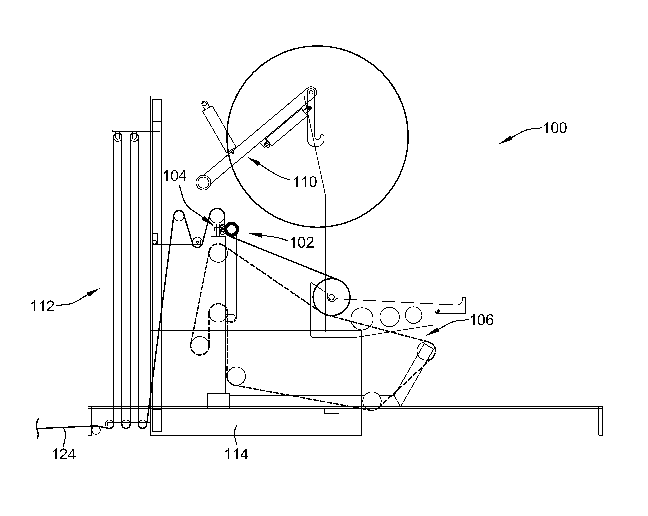
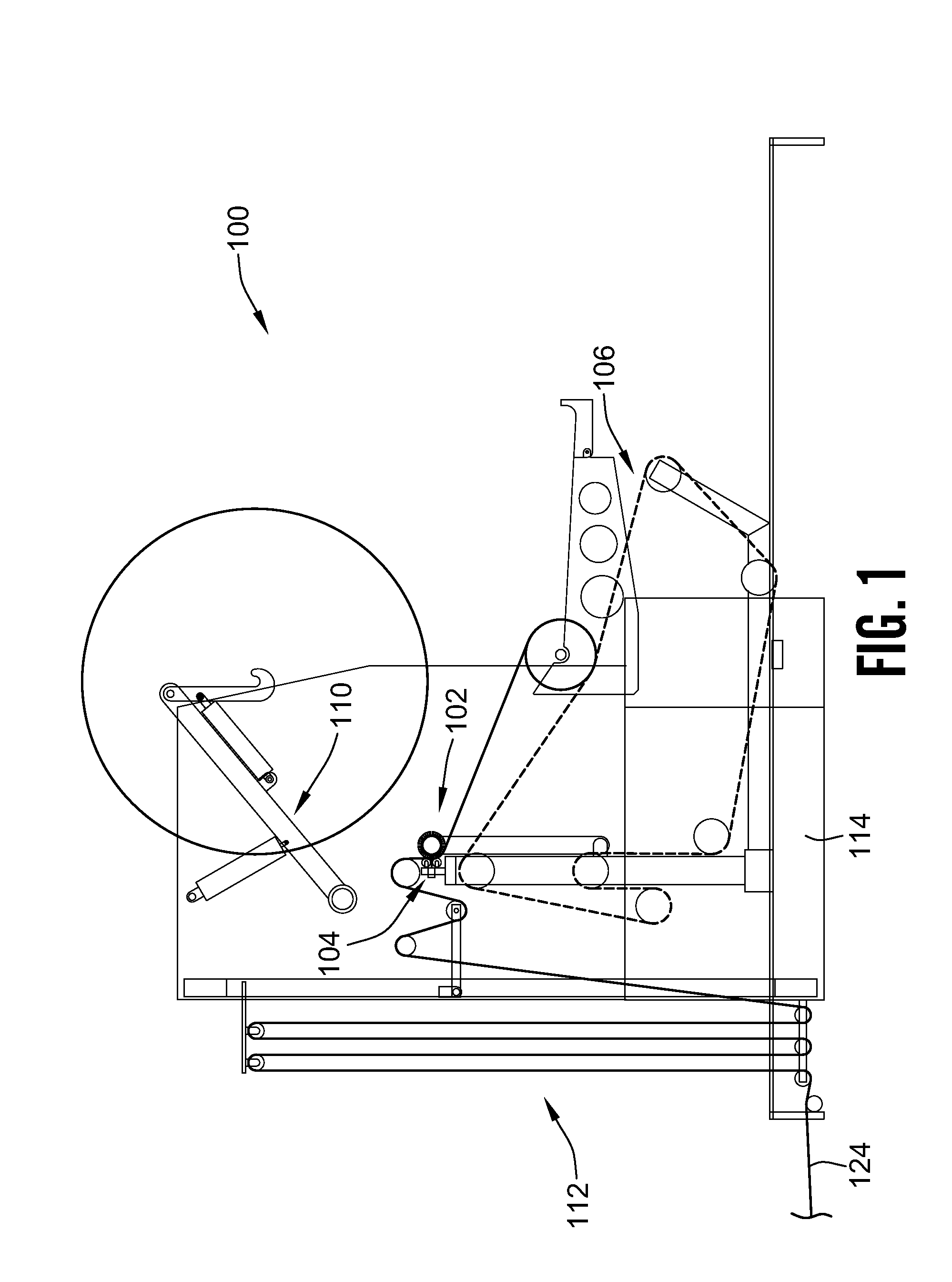
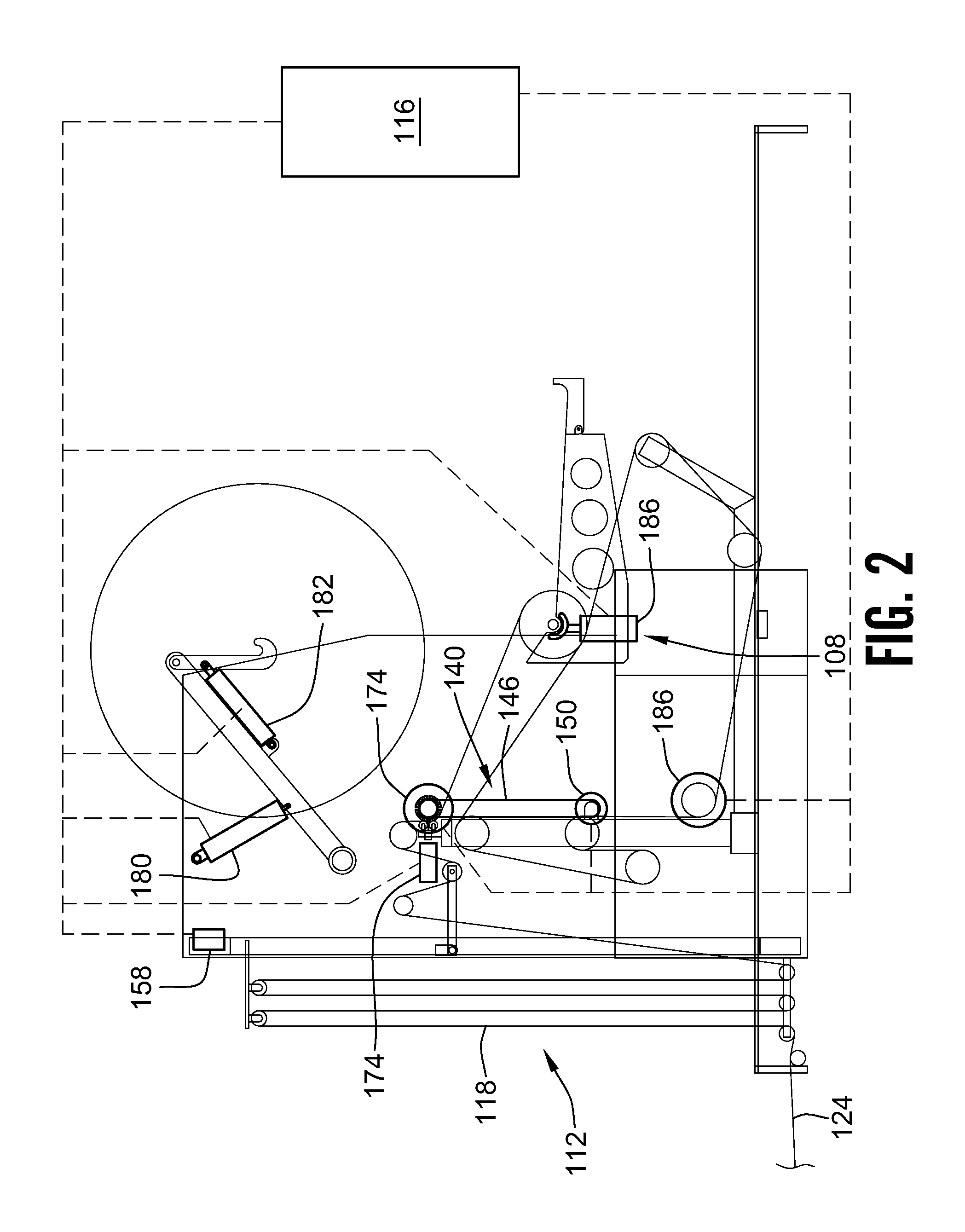
[0075]FIGS. 1 and 2 show a first exemplary embodiment 100 of an automated unwind stand with auto-splicing capability. The exemplary embodiment of the unwind stand 100 includes: a splicing arrangement 102, a cutting arrangement 104, a coil drive arrangement 106, a spent coil ejection arrangement 108, a staged coil handling arrangement 110 and a web accumulator arrangement 112, all mounted in a frame 114 of the unwind stand 100. As shown in FIG. 2, the exemplary embodiment of the unwind stand 100 also includes a controller 116, which is operatively connected to actuators and motors in various parts of the unwind stand 100, for automated operation of the stand 100 as described in more detail below. Those having skill in the art will appreciate that, although the controller 116 is shown as a single unit in the exemplary embodiment of the unwind stand 100, in other embodiments of the invention the controller may be broken into a number of separate units some of which operate automaticall...

exemplary embodiment 200

[0106]Regarding the drawing FIGS., it will be noted that FIGS. 12-15 are generally applicable to both the first and second exemplary embodiments of the unwind stand 100, 200, with the exception that in the second exemplary embodiment 200 the strip of tape 154 shown in FIGS. 12-15 is not used.

[0107]In the second exemplary embodiment of the automated unwind stand 200, once the second coil 134 is mounted in the staged position, as shown in FIG. 3, the operator initiates the auto-splicing process through the controller 116.

[0108]The accumulator arrangement 112, in the exemplary embodiment of the unwind stand 100, takes the form of a festoon arrangement, of the type generally known in the art having a series of pulleys about which the first web 118 is threaded. Some of the pulleys are moveable by a festoon actuator 158, in the manner illustrated in FIG. 2, for storing a length of the first web 18 in the festoon to provide a continuous feed of web 118 along the web path 124 during the aut...


PUM

PropertyMeasurementUnit
Pressureaaaaaaaaaa
Speedaaaaaaaaaa
Distanceaaaaaaaaaa

Abstract

A splice is made, between a tail end of first web and a lead end of a second web coiled about an unwind axis, by winding a portion of the first web adjacent the tail end of the first web about a splicing roll mounted for rotation about a splice roll axis oriented substantially parallel to the unwind axis, and then joining the tail end to the lead end by compressing an adhesive between an inside surface of the tail end and an outer surface of the second web. Compression of the adhesive is accomplished by urging the splice roll against the coiled second web while the coiled second web is rotating about the unwind axis in an unwind direction and the splicing roll is rolling about the splice roll axis in a direction opposite to the unwind direction.

Description

CROSS-REFERENCE TO RELATED PATENT APPLICATIONS[0001]This patent application claims the benefit of U.S. Provisional Patent Application No. 61 / 170,449, filed Apr. 17, 2009, the disclosure and teachings of which are incorporated herein, in their entireties, by reference.FIELD OF THE INVENTION[0002]This invention relates to a method and apparatus for feeding a continuous web of paper or like material into a rotary press, folding machine, or other machine. More specifically, the invention relates to a method and apparatus for automated splicing of successive rolls of the web either with or without the need for suspending the feeding of the web along the feed path.BACKGROUND OF THE INVENTION[0003]Many types of flexible materials such as paper, plastic and fabric are coiled into rolls and shipped to an end-user or processor. Typically, the coiled material is mounted on an unwind stand which allows the web of material to be unwound in a controlled fashion so that it can be converted into a ...

Claims


Application Information

Patent Timeline
IPC IPC(8): B65H19/18B65H21/00B65H19/20B65H19/14
CPCB65H19/1847B65H2301/41361B65H2301/41892B65H2301/46172B65H2301/4621B65H2408/2171B65H2301/4633B65H2403/942B65H2406/33B65H2408/216B65H2301/46312B65H2301/41732B65H2301/41734
Inventor BUTTERWORTH, TAD T.
Owner C G BRETTING MFG
Why Eureka
Try Eureka