

LED lamp
a technology of led lamps and led lamps, which is applied in the direction of discharge tube main electrodes, semiconductor devices for light sources, lighting and heating apparatus, etc., can solve the problems of limited illumination area of led lamps and the inability of led lamps to obtain the desired illumination area
- Summary
- Abstract
- Description
- Claims
- Application Information
AI Technical Summary
Benefits of technology
Problems solved by technology
Method used
Image

Examples
first embodiment
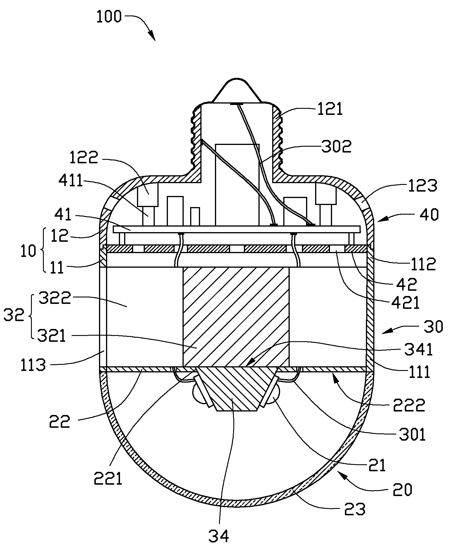
[0018]Referring to FIG. 1, an LED lamp 100 includes a hollow lamp housing 10, an optical part 20, a heat dissipation part 30, and an electrical part 40. The LED lamp 100 is substantially cylindrical. The optical part 20 is arranged at a front end of the LED lamp 100. The electrical part 40 is arranged at a rear end of the LED lamp 100. The heat dissipation part 30 is located between the optical part 20 and the electrical part 40. The heat dissipation part 30 and the electrical part 40 are received in the lamp housing 10.
[0019]The lamp housing 10 includes a front shell 11 and a rear shell 12 connected to the front shell 11. The front shell 11 is a hollow cylinder, and has a front end 111 and an opposite rear end 112. The heat dissipation part 30 is arranged in the front shell 11, while the electrical part 40 is arranged in the rear shell 12. The rear shell 12 is cup-shaped. The rear shell 12 has an open front end connected with the rear end 112 of the front shell 11, and a rear scre...
second embodiment
[0035]Referring to FIGS. 6-7, an LED lamp 100a is illustrated. The difference between the present LED lamp 100a and the LED lamp 100 illustrated in FIG. 1 lies in the heat dissipation part 30a and the optical part 20a. In the present embodiment, the heat dissipation part 30a further includes a heat pipe 36 connecting the mounting seat 34 with the heat sink 32, and a light reflector 22a of the optical part 20a has a configuration of a dishware. The light sources 21, the mounting seat 34, the heat pipe 36 and the heat sink 32 cooperatively form a light engine 31a for the LED lamp 100a.
[0036]It is well known in the art that a heat pipe is a sealed hollow pipe body receiving working fluid therein and containing a wick structure disposed on an inner wall of the pipe body. The heat pipe 36 transfers heat under phase change of working fluid hermetically contained therein. The heat pipe 36 is elongated and includes a front evaporating section 361 connecting with the mounting seat 34 and a...
third embodiment
[0039]Referring to FIG. 9, an LED lamp 100b is illustrated. The difference between the present LED lamp 100b and the LED lamp 100a illustrated in FIG. 6 lies in the heat dissipation part 30b. In the present embodiment, the heat dissipation part 30b further includes a cooling fan 35 provided between the electrical part 40 and the heat sink 32.
[0040]The cooling fan 35 is located at a rear side of the heat sink 32. The front shell 11b defines radially a plurality of air exchanging holes 133b corresponding to the fins 322 of the heat sink 32 and a plurality of air openings 115 in a rear end thereof adjacent to the rear shell 12. The air openings 115 of the front shell 11 function as air supply openings or air exhausting openings for the cooling fan 35. When the cooling fan 35 operates, the cooling fan 35 inhales air from the ambient atmosphere via the air openings 115 defined in the rear end of the front shell 11. An airflow generated by the cooling fan 35 flows towards the heat sink 3...
PUM
 Abstract
Description
Claims
Application Information