
Usb/esata combo receptable featured with ground layer retarding interfaces therebetween

a ground layer retarding and combo technology, applied in the direction of coupling device details, coupling device connections, electric discharge lamps, etc., can solve the problem of weakening the capability of the connector

Inactive Publication Date: 2010-10-21
HON HAI PRECISION IND CO LTD
View PDF3 Cites 122 Cited by
  • Summary
  • Abstract
  • Description
  • Claims
  • Application Information

AI Technical Summary

Problems solved by technology

It can be readily seen from the disclosure of the Chiang '116 patent that cross-talk will be produced between the eSATA contact set and the USB contact set, which may weaken the capability of the connector.

Method used


Image

  • Usb/esata combo receptable featured with ground layer retarding interfaces therebetween
  • Usb/esata combo receptable featured with ground layer retarding interfaces therebetween
  • Usb/esata combo receptable featured with ground layer retarding interfaces therebetween

Examples


Embodiment Construction

[0014]Reference will now be made to the drawing figures to describe the preferred embodiment of the present invention in detail.

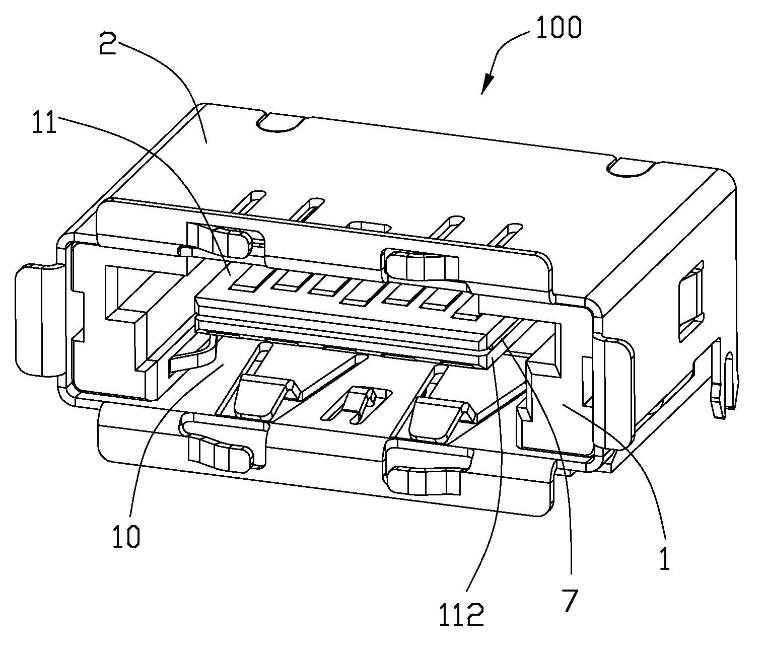
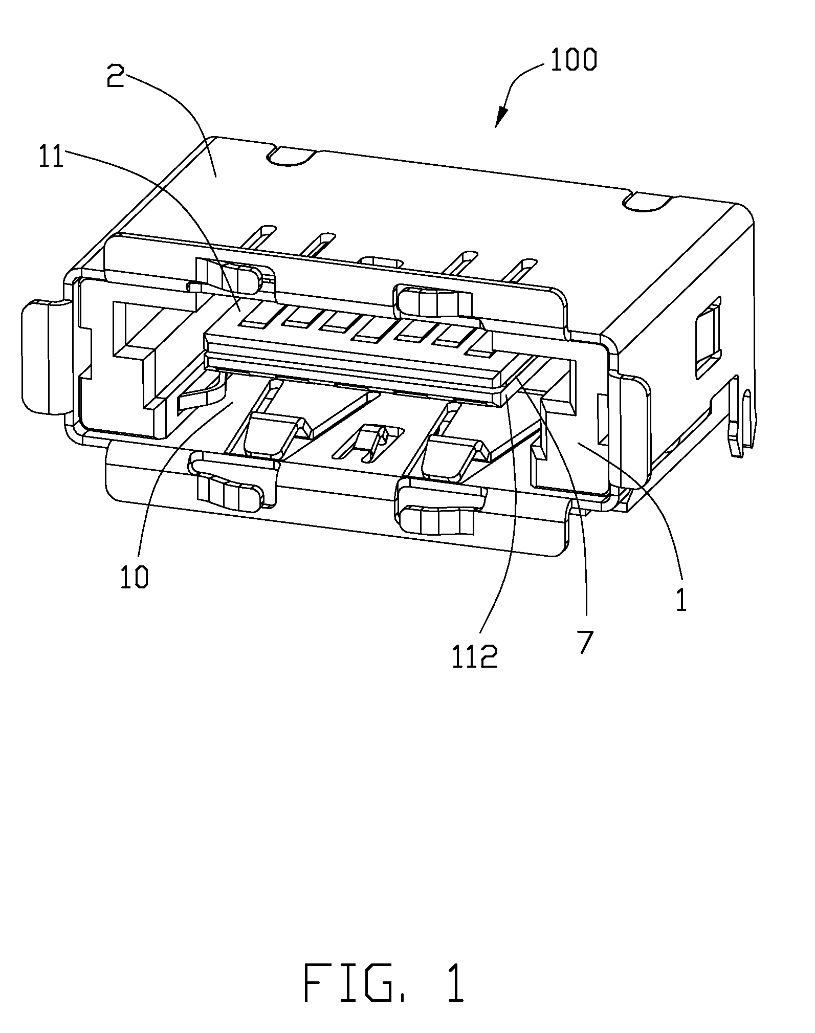
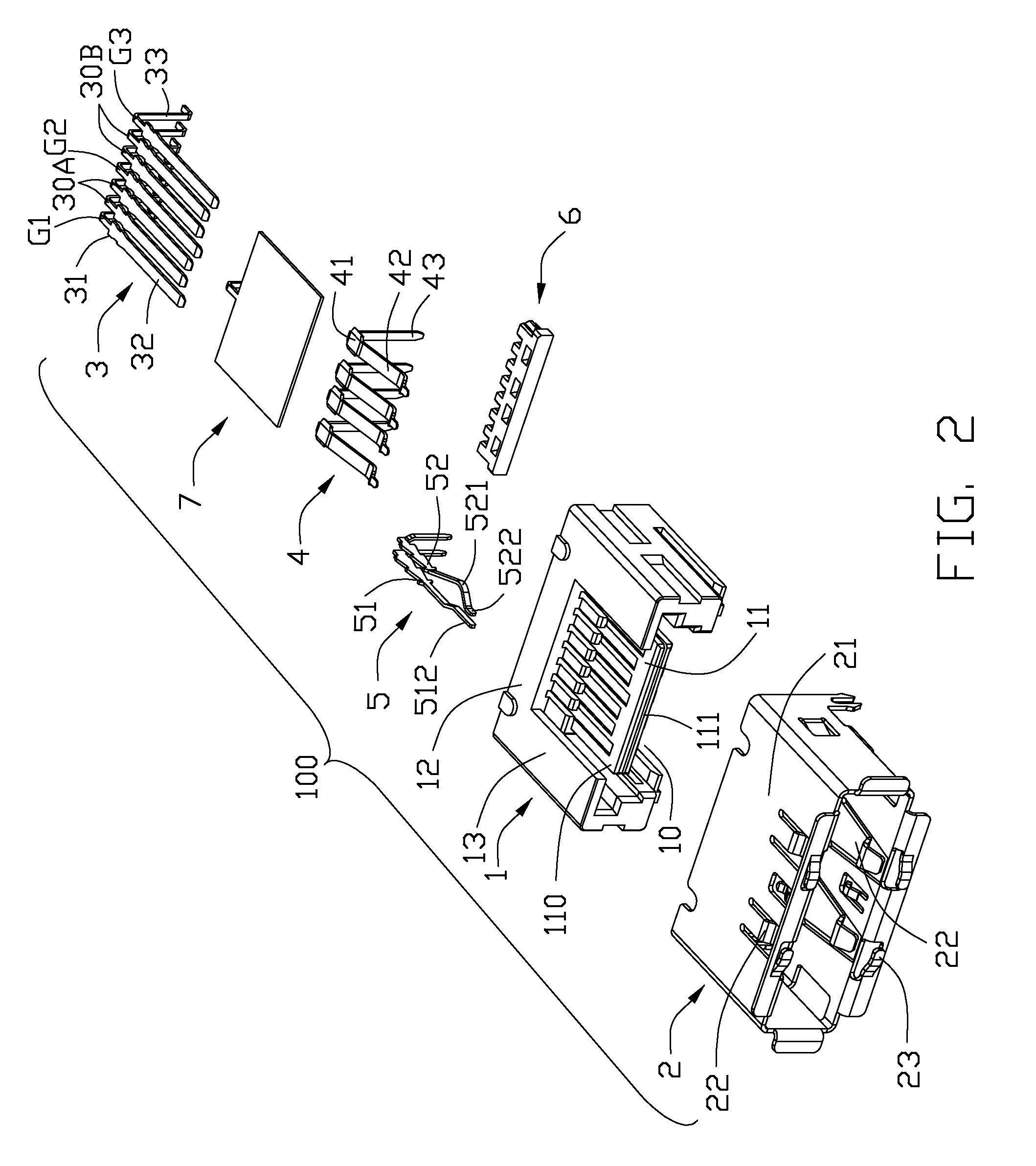
[0015]Referring to FIG. 1, disclosed here is an electrical connector 100 made in accordance with the present invention. The electrical connector 100, compatible to standards of Universal Serial Bus (USB) and External Serial Advanced Technology Attachment (eSATA) protocols, includes an insulative housing 1, a shielding shell 2 surrounding the housing 1, sets of contact retained to the housing 1 and a grounding member 7 disposed in the housing 1.

[0016]Referring to FIG. 1 to FIG. 4, the housing 1 defines a base portion 12, a pair of sidewalls 13 respectively extending forwards from two opposite ends of the base portion 12, a mating cavity 10 defined by the pair of sidewalls 13 and the base portion 12 commonly and two mating portions A, B spaced from each other and respectively extending forwards from the base portion 12 and into the mating cavity 10 along a ma...


PUM


Abstract

An electrical connector includes an insulative housing defining a mating cavity, two parallel and stacked mating portions respectively forwards extending into the mating cavity, sets of contact retained in the housing and a grounding member retained in the housing. The first mating portion defines thereon a first surface; the second mating portion spaces from the first mating portion and defines thereon a second surface opposite to the first surface. The sets of contact include a first set of contacts each defining a contacting section exposed upon the first surface and a second set of contacts each defining a deflectable cantilevered beam accessible from the second face. The grounding member is disposed between the first and second mating portions to reduce the cross-talk between the first and second sets of contacts.

Description

CROSS-REFERENCE TO RELATED APPLICATIONS[0001]This application is related to U.S. patent application Ser. No. 12 / 630,725, filed on Dec. 3, 2009 and entitled “RECEPTACLE CONNECTOR HAVING SHUTTLE TO SELECTIVELY SWITCH TO DIFFERENT INTERFACES”; U.S. patent application Ser. No. 12 / 701,607, filed on Feb. 8, 2010 and entitled “ELECTRICAL CONNECTOR FEATURED USB / eSATA INTERFACES”; and U.S. patent application Ser. No. 12 / 702,293 filed on Feb. 9, 2010 and entitled “ELECTRICAL CONNECTOR FEATURED USB / eSATA INTERFACES INCORPORATED WITH ADDITIONAL POWER CONTACT”; all of which have the same assignee as the present invention.BACKGROUND OF THE INVENTION[0002]1. Field of the Invention[0003]The present invention relates to an electrical connector, and more particularly to an electrical connector compatible to standards of Universal Serial Bus (USB) and External Serial Advanced Technology Attachment (eSATA) protocols and having a grounding member which is disposed between the USB contact set and the eSA...

Claims


Application Information

Patent Timeline
IPC IPC(8): H01R27/00
CPCH01R13/6461
Inventor LIN, CHIH-NANHSU, KUO-CHUNYU, HUNG-CHI
Owner HON HAI PRECISION IND CO LTD
Learn More