Chemical sensor with oscillating cantilevered probe and mechanical stop

a cantilevered probe and chemical sensor technology, applied in the field of chemical sensing methods, can solve the problems of inconvenient sampling, inconsistent and inaccurate results, and damage to the tip or sample, and achieve the effects of improving the accuracy of the sampl

Active Publication Date: 2009-04-21
BOARD OF RGT NEVADA SYST OF HIGHER EDUCATION ON BEHALF OF THE UNIV OF NEVADA RENO
View PDF133 Cites 52 Cited by
  • Summary
  • Abstract
  • Description
  • Claims
  • Application Information

AI Technical Summary

Problems solved by technology

Biological samples have been difficult to scan using contact mode because they are weakly secured to the surface and can be easily scraped off.
With the constant-height mode, the force applied to the sample increases with cantilever deflection, which may result in damage to the tip or the sample.
In the constant force mode, however, variations in sample compressibility may yield inconsistent and inaccurate results.
Current methods for detecting AFM cantilevers generally use optical methods, though these systems require comparably high power, need alignment, have limited resolution, and are prone to drift because of the size of the optical path and the need to retain all parts and optical elements securely coupled to each other.
Current systems typically require external lighting for sample illumination and setup, and are not very compact because of the long optical path, the need to have the photodetector at an ample distance from the sample, and constrained viewing and positioning systems for optical alignment.
Sample testing in liquids such as water or saline solution presents additional difficulties for optical sensing due to aberrations and refraction of the light beam traversing the fluid.
Piezoresistive sense methods are more compact and may have more resolution than optical systems, though they can self-heat and cause drift.
Furthermore, piezoresistive sensing typically consumes large portions of available power when used in a portable device.
Piezoelectric devices are generally not selected for static bending measurements due to leakage and charge decay issues of many piezoelectric films.
Chemical sensing with static or quasi-static cantilever bending and piezoelectric sensing in response to chemical exposure is difficult due to the minute deflection changes of the cantilever curvature and the tendency of detection systems to drift.

Method used


Image

  • Chemical sensor with oscillating cantilevered probe and mechanical stop
  • Chemical sensor with oscillating cantilevered probe and mechanical stop
  • Chemical sensor with oscillating cantilevered probe and mechanical stop

Examples


Embodiment Construction

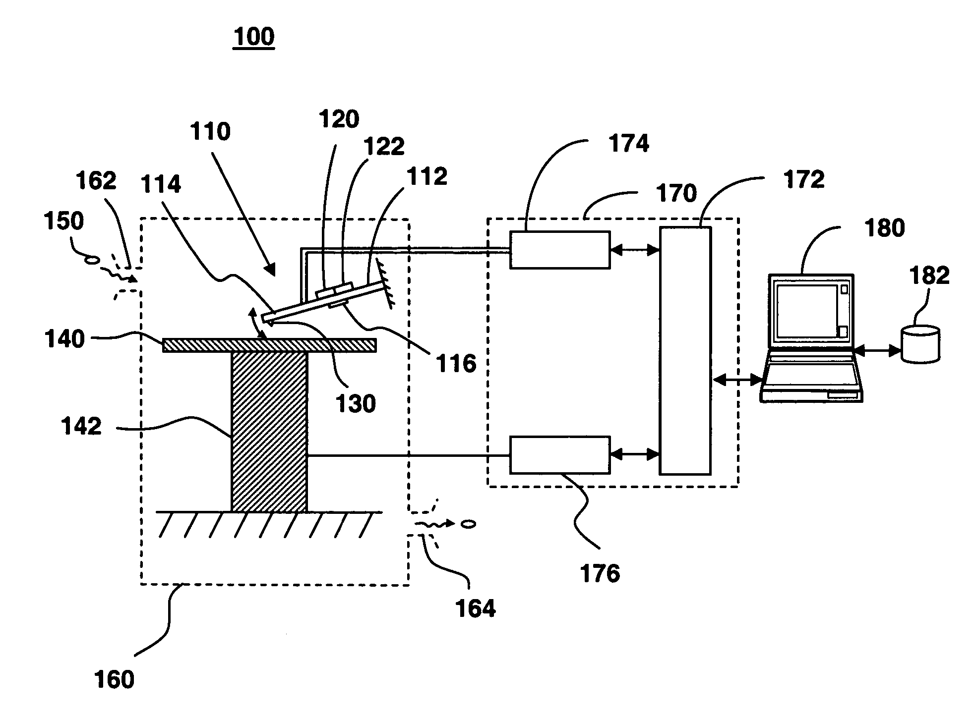
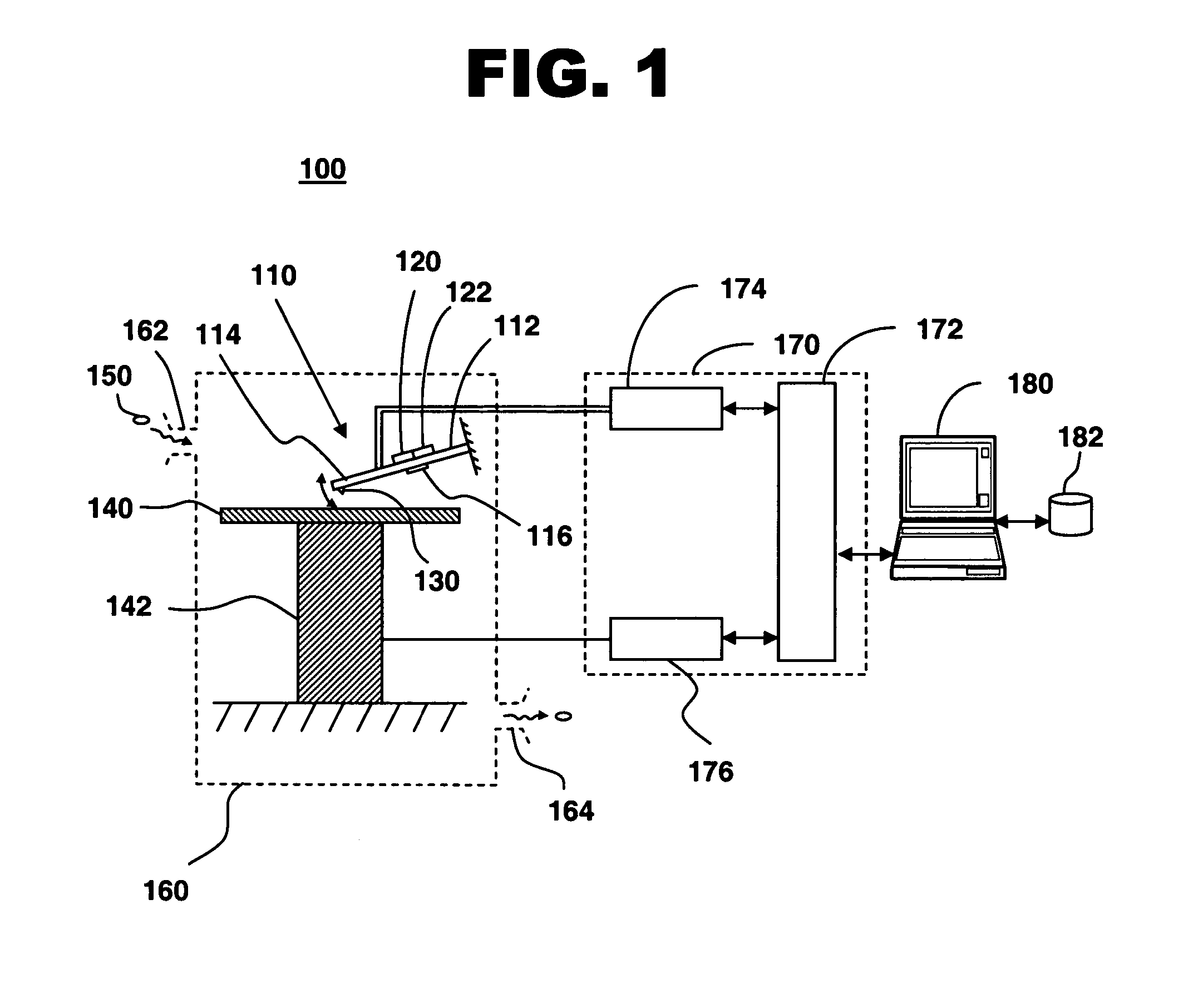
[0035]FIG. 1 illustrates a system for sensing a chemical species, in accordance with one embodiment of the present invention at 100. Chemical-sensing system 100 includes a cantilevered beam 110, a drive mechanism 120 coupled to cantilevered beam 110, a sense mechanism 122 coupled to cantilevered beam 110, and a mechanical stop 140. Cantilevered beam 110 is driven into oscillation with drive mechanism 120, and oscillating cantilevered beam 110 is tapped against mechanical stop 140. Amplitudes of oscillation are measured, and changes in the oscillation amplitude are measured after exposing cantilevered beam 110 to a chemical species 150 to detect or sense the chemical species. Chemical species 150 is determined based on oscillation amplitudes of cantilevered beam 110 measured by sense mechanism 122 when a treated portion 116 of cantilevered beam 110 is exposed to chemical species 150.

[0036]Cantilevered beam 110 includes a base end 112 rigidly attached to a support. Cantilevered beam 1...


PUM

PropertyMeasurementUnit
chemical-sensitiveaaaaaaaaaa
frequencyaaaaaaaaaa
dielectricaaaaaaaaaa

Abstract

The invention provides a method of detecting a chemical species with an oscillating cantilevered probe. A cantilevered beam is driven into oscillation with a drive mechanism coupled to the cantilevered beam. A free end of the oscillating cantilevered beam is tapped against a mechanical stop coupled to a base end of the cantilevered beam. An amplitude of the oscillating cantilevered beam is measured with a sense mechanism coupled to the cantilevered beam. A treated portion of the cantilevered beam is exposed to the chemical species, wherein the cantilevered beam bends when exposed to the chemical species. A second amplitude of the oscillating cantilevered beam is measured, and the chemical species is determined based on the measured amplitudes.

Description

CROSS-REFERENCE TO RELATED APPLICATIONS[0001]This utility application claims the priority benefit of U.S. Provisional Application No. 60 / 447,172, filed Feb. 11, 2003.STATEMENT OF GOVERNMENT RIGHTS[0002]This invention was made with Government support under Contract No. DE-AC05-00OR22725 awarded by the United States Department of Energy to the University of Nevada, Reno and the Government has certain rights in this invention.FIELD OF THE INVENTION[0003]This invention relates generally to chemical-sensing methods, and in particular, relates to a method and system for sensing specific chemicals and biological materials using a treated cantilever of an atomic force microscope operating in a tapping mode against a mechanical stop.BACKGROUND OF THE INVENTION[0004]Micromachined cantilevers, as used in atomic force microscopy (AFM), hold promise in chemical-sensing applications, and may become the basis for specialized, ultraminiature, ultrasensitive sensors for detection of specific target ...

Claims


Application Information

Patent Timeline
Patent Type & Authority Patents(United States)
IPC IPC(8): G01N33/00G01N27/00H01J3/14G01Q60/24G01Q60/34G01Q70/18
CPCG01Q60/34G01Q60/42G01Q70/08B82Y35/00
Inventor ADAMS, JESSE D.ROGERS, BENJAMIN S.
Owner BOARD OF RGT NEVADA SYST OF HIGHER EDUCATION ON BEHALF OF THE UNIV OF NEVADA RENO
Why Eureka
Try Eureka