Optical-fiber grating sensor detecting pressure temperature simultaneously

A fiber grating and sensor technology, applied in the field of fiber grating sensors, achieves the effects of good safety, avoiding chirp phenomenon, and improving resolution

Inactive Publication Date: 2002-12-11
TSINGHUA UNIV
View PDF0 Cites 61 Cited by
  • Summary
  • Abstract
  • Description
  • Claims
  • Application Information

AI Technical Summary

Problems solved by technology

[0005] The purpose of the present invention is to provide a fiber grating sensor for simultaneous detection of pressure and temperature to overcome the deficiencies of the prior art. It can not only real

Method used


Image

  • Optical-fiber grating sensor detecting pressure temperature simultaneously
  • Optical-fiber grating sensor detecting pressure temperature simultaneously
  • Optical-fiber grating sensor detecting pressure temperature simultaneously

Examples


Embodiment Construction

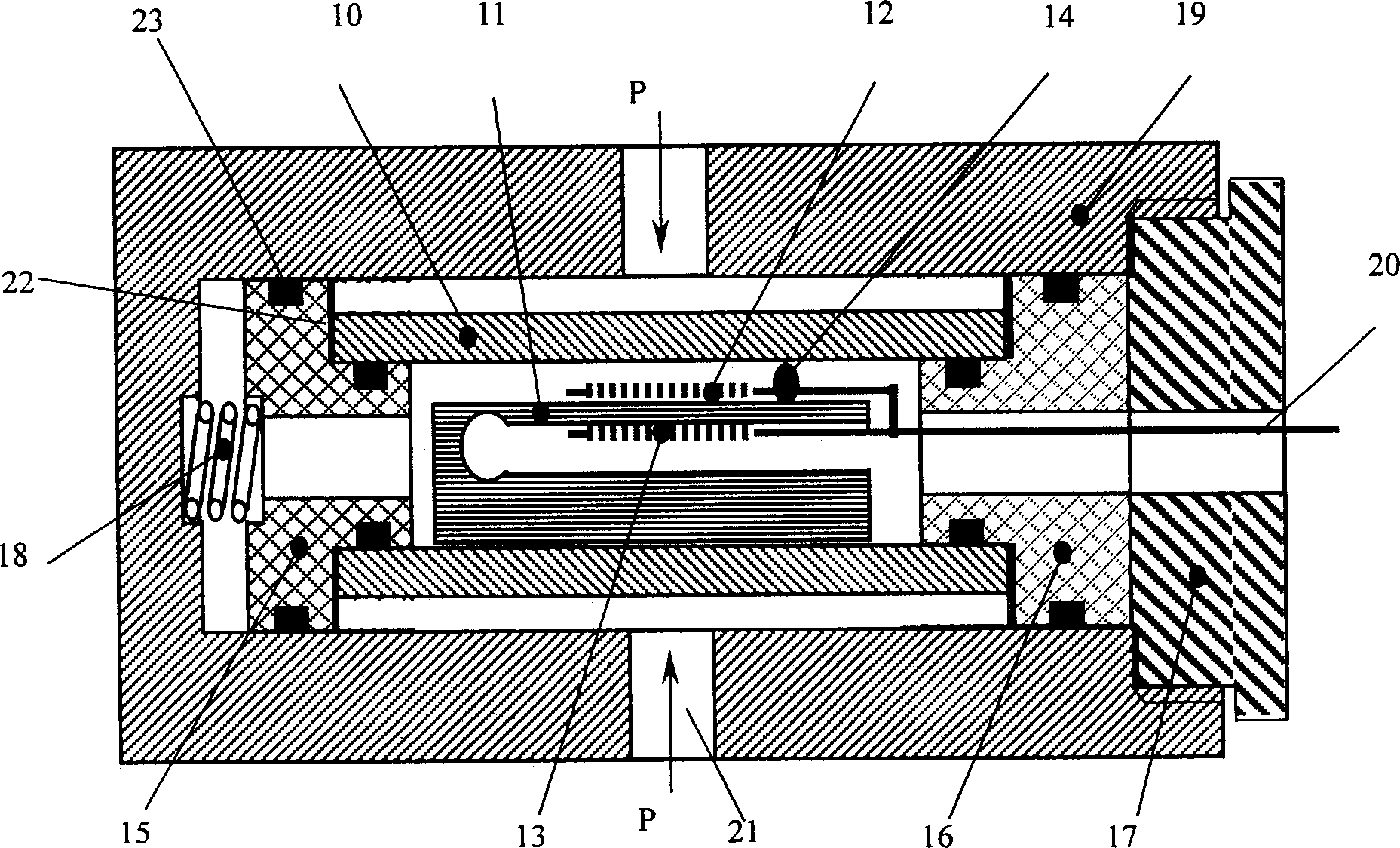
[0022] The measurement principle, specific structure and best implementation mode of the present invention will be further described below in conjunction with the accompanying drawings.

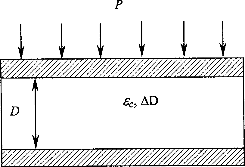
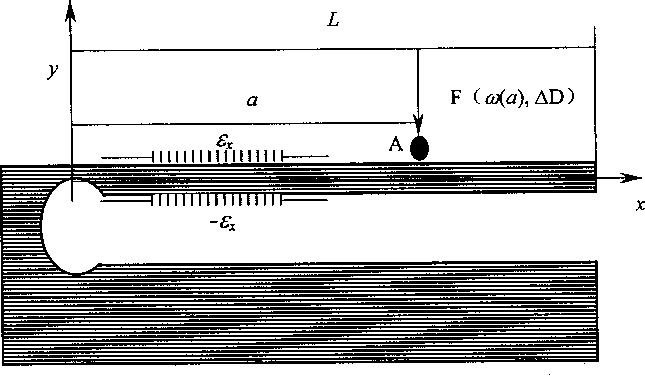
[0023] figure 1 It is a structural schematic diagram of the sensor of the present invention. The sensor mainly includes a free elastic cylindrical pressure transducer 10, a cantilever beam mechanism 11 placed in the free elastic cylindrical pressure transducer, a transmission optical fiber 20, sealing mechanisms 15, 16, pre-tension spring 18, belt There is an outer protective shell 19 with a pressure inlet hole 21 and an end element 17 for positioning. The cantilever beam mechanism 11 adopts an isosceles triangle structure of equal thickness (such as image 3 , 4 As shown), two fiber gratings 12 and 13 are fixed respectively on the corresponding positions of the upper and lower surfaces of the cantilever beam 11. These two fiber gratings have the same parameters and performance, and are co...


PUM


Abstract

The optical fiber grating sensor detecting pressure and temperature simultaneously consists of mainly free elastic cylindrical pressure transducer, cantilever beam mechanism, fiber grating, sealed part, end element and pre-tensed spring; protective casing and transmission fiber. The technological scheme is that two fiber gratings are fixed to the upper and the lower surface of the cantilever beamin the corresponding positions and connected to transmission fiber via one fiber coupler; that the triangular cantilever beam mechanism converts the radial information of the cylinder under the outer pressure into deflection of the cantilever beam and thus the variation of the Bragg reflection wavelength with temperature and pressure, and that differential measurement technology is used to solvethe cross sensitivity of fiber grating.

Description

technical field [0001] The invention relates to an optical fiber grating sensor, in particular to an optical fiber grating sensor for simultaneous detection of pressure and temperature, and belongs to the technical field of precision measurement. technical background [0002] For the measurement of pressure and temperature parameters such as oil wells and seabeds, traditional electrical measurement methods are often used. By using different sensors (usually platinum resistance thermometers for temperature, strain gauges or capacitance sensors for pressure), temperature and The pressure is detected separately, and then the signal is transmitted to the survey ship on the sea surface or the logging device on the bottom surface through the cable, and then the signal is processed by the analysis instrument. The biggest disadvantage of this method is that the electrical signal is easily affected by the harsh environment of the underground. Because it contains electrical signals, t...

Claims


Application Information

Patent Timeline
IPC IPC(8): G01D5/26G01D21/02
Inventor 赵勇廖延彪
Owner TSINGHUA UNIV
Why Eureka
Try Eureka