
Supercharger mechanism and anchor rod comprehensive mechanical performance test platform thereof

A test platform and pressure technology, applied in the testing of machine/structural components, testing of mechanical components, scientific instruments, etc., can solve problems such as complex mechanical changes of anchor bolts

Active Publication Date: 2019-03-15
ANHUI UNIV OF SCI & TECH
View PDF5 Cites 8 Cited by
  • Summary
  • Abstract
  • Description
  • Claims
  • Application Information

AI Technical Summary

Problems solved by technology

These are not considered in the above-mentioned patents. In actual use, the roadway designer often infers the selection requirements and construction methods of the bolt through the analysis of the rock and soil of the roadway and the mechanical analysis of the bolt. However, this is an ideal situation. In the actual construction and use process, the mechanical changes of the anchor are very complicated. Therefore, the applicant believes that the test of the mechanical properties of the anchor should not simply test the various forces on the anchor directly, but simulate During the construction of the anchor bolt, the change of the rock and soil after construction, and the comprehensive stress applied to the anchor bolt at the same time are tested

Method used


Image

  • Supercharger mechanism and anchor rod comprehensive mechanical performance test platform thereof
  • Supercharger mechanism and anchor rod comprehensive mechanical performance test platform thereof
  • Supercharger mechanism and anchor rod comprehensive mechanical performance test platform thereof

Examples


Embodiment Construction

[0075] Below in conjunction with accompanying drawing and embodiment the present invention will be further described:

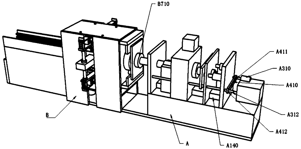
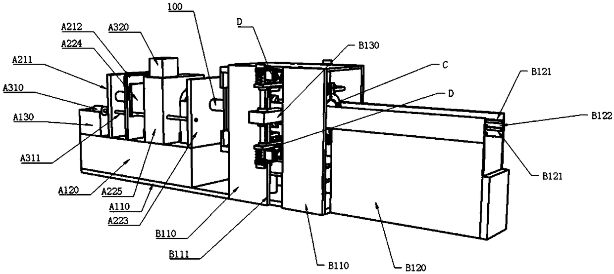
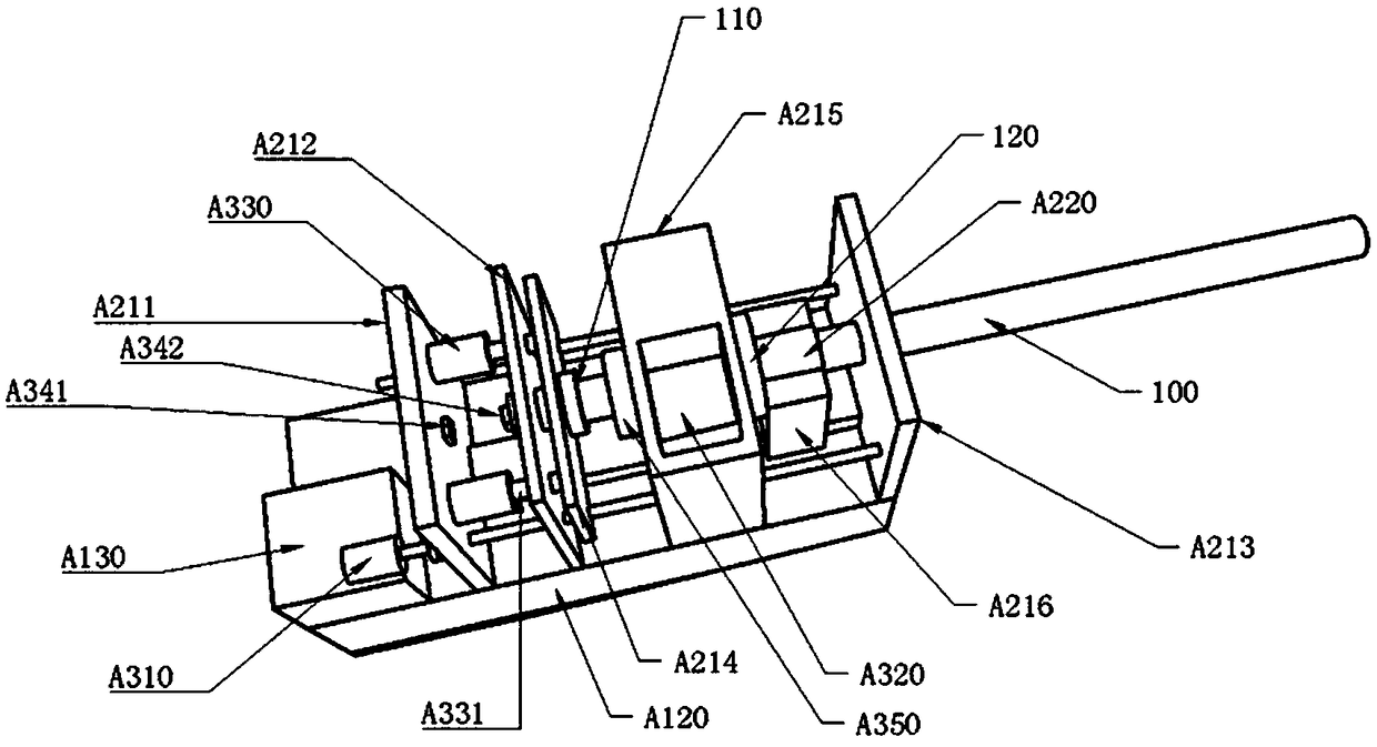
[0076] see Figure 1-Figure 25 , the test platform for the comprehensive mechanical properties of anchor rods in this embodiment includes an anchoring mechanism A and an anchoring mechanism B. The anchoring mechanism A includes an anchoring base plate A110 on which an anchoring support seat is fixed A120, the anchoring support seat A120 is fixed with an anchoring motor seat A130, an anchoring slide rail A140, a first anchoring vertical plate A211, a second anchoring vertical plate A212, and a third anchoring vertical plate A213. An anchor motor A310 is installed on the anchor motor seat A130, and the anchor slide rail A140 is slidably assembled with the anchor torque seat A215 and the anchor guide seat A216 respectively, and the output shaft of the anchor motor A310 is connected to the first drive screw rod A311 One end is connected and fixed, and the anchor...


PUM


Abstract

The invention discloses a supercharging mechanism and an anchor rod comprehensive mechanical performance test platform thereof. The supercharging mechanism comprises a fulcrum assembly, wherein the fulcrum assembly is mounted at the end, far away from a first pressure connecting rod and a second pressure connecting rod, of a pressure applying plate; the fulcrum assembly comprises a fulcrum supportplate which is fixed on the pressure applying plate; a step-down sliding slot is formed in the fulcrum support plate; the step-down sliding slot is glidingly assembled with a limit sliding rod; one end of the limit sliding rod is fixedly connected with a telescopic support plate; the limit sliding rod passes through one end of a stop plate to be fixedly connected with one end of a first fulcrum spring; the other end of the first fulcrum spring is fixedly connected with the pressure applying plate; the telescopic support plate is assembled and fixed with each of the first fulcrum support plateand the second fulcrum support plate; a fulcrum switching electromagnet is mounted between the first fulcrum support plate and the second fulcrum support plate; and the fulcrum switching electromagnet is assembled with one end of a fulcrum switching telescopic shaft; and the other end of the fulcrum switching telescopic shaft passes through the second fulcrum support plate to be assembled and fixed with a fulcrum block.

Description

technical field [0001] The invention relates to a test device, in particular to a pressurization mechanism and a test platform for comprehensive mechanical properties of a bolt. Background technique [0002] In the Chinese invention patent whose publication number is CN104075943B, a kind of test bench and test method for testing the comprehensive mechanical properties of anchor rods are disclosed. The test mechanism and the bending load test mechanism, axial load test mechanism, shear load test mechanism and impact load test mechanism set on the working test bench; through this test bench, the bolt installation and working process can be simulated in the laboratory, and Apply single or multiple combined external forces such as torsion, tension, bending, shearing and impact to the anchor; use independent loading systems to apply corresponding loads to the anchor, and can perform various loads in the installation and working process of the anchor respectively. The independent...

Claims


Application Information

Patent Timeline
IPC IPC(8): G01N3/00G01N3/02G01M13/00G09B25/00
CPCG01M13/00G01N3/00G01N3/02G01N2203/0026G09B25/00
Inventor 梁书玲赖钰媛
Owner ANHUI UNIV OF SCI & TECH
Learn More