
Rock relaxation test mechanism and test apparatus of same

A technology of testing mechanism and experimental device, which is applied in the direction of measuring device, testing material strength by using one-time impact force, instrument, etc. It can solve the problems of sample displacement, manual adjustment of pendulum, injury, etc., and achieve effective fixation and rapid assembly Effect

Active Publication Date: 2017-10-24
ANHUI UNIV OF SCI & TECH
View PDF8 Cites 8 Cited by
  • Summary
  • Abstract
  • Description
  • Claims
  • Application Information

AI Technical Summary

Problems solved by technology

Although this method is simple and feasible, it is very troublesome to manually adjust the pendulum and constantly calculate the impact force generated by the angle of the pendulum.
In addition, there is a great potential safety hazard during the impact of the pendulum rotation. If the operator is negligent, it is likely to be injured or hit other objects.
[0005] In addition, when performing relaxation-disturbance experiments, it is sometimes necessary to apply confining pressure to the rock sample, which requires filling the space where the sample is located with hydraulic oil, which means that openings need to be provided for the space where the sample is located. And it must be able to ensure the sealing of this opening; of course, some experiments can be directly replaced by triaxial testing machines, but most of the openings of triaxial testing machines are directly below and the direction of sample placement is the vertical direction perpendicular to the ground , but placed in the horizontal direction due to insufficient width or length. In addition, when clamping the sample, the general triaxial testing machine generally compresses the sample in the axial direction of the sample first, and then seals and fastens the loading shell. , this total will easily lead to sample displacement and affect the experimental results

Method used


Image

  • Rock relaxation test mechanism and test apparatus of same
  • Rock relaxation test mechanism and test apparatus of same
  • Rock relaxation test mechanism and test apparatus of same

Examples


Embodiment Construction

[0077] Below in conjunction with accompanying drawing and embodiment the present invention will be further described:

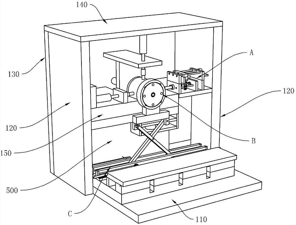
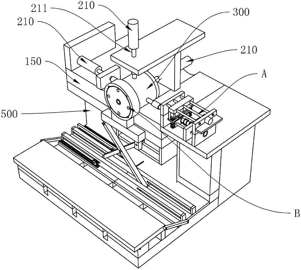
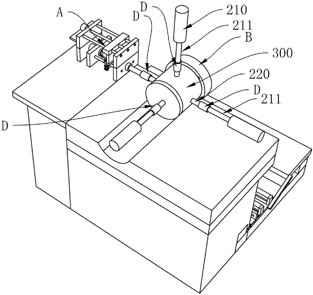
[0078] see Figure 1-Figure 3 , a relaxation-disturbance comprehensive experimental device, comprising a frame, a disturbance generating mechanism A, a relaxation testing mechanism; the frame includes, a bottom plate 110, a side plate 120, a rear plate 130, a top plate 140, and the side plate 120. The bottom and top of the rear plate 130 are respectively connected and fixed to the bottom plate 110 and the top plate 140, and a supporting plate 150 is connected and fixed between the two side plates 120, and an oil tank 500 for storing hydraulic oil is provided under the supporting plate 150;

[0079] The supporting plate 150 is fixed with a slack testing mechanism and a disturbance generating mechanism A. The slack testing mechanism includes a loading cylinder 210. There may be three loading cylinders 210 and they are respectively arranged with the loading shel...


PUM


Abstract

The invention discloses a rock relaxation test mechanism, which includes a loading oil cylinder, a loading shell, a loading shaft, a cover plate assembly, and a lifting assembly. A loading cavity is formed in the loading shell. The loading shaft passes through the loading shell and enters the loading cavity. A rock sample is mounted in the loading cavity. A clamping screw is arranged on an opening end surface of the loading shell and is mounted in a clamping hole in the cover plate assembly so as to mounting the cover plate assembly with the loading shell. The invention also discloses a relaxation-disturbance comprehensive test apparatus using the rock relaxation test mechanism. The test apparatus can be used for carrying out the relaxation-disturbance comprehensive test, can restore the actual forced status of the sample underground relatively actually, and can supply effective reference for design and construction in later period.

Description

technical field [0001] The invention relates to a rock mechanics experiment device, in particular to a rock relaxation test mechanism and a test device thereof. Background technique [0002] Stress rheological phenomena can be seen everywhere in rock mass engineering. For example, after some underground chambers, roadways, tunnels, etc. are excavated and supported, rocks will undergo rheological phenomena after a period of time, and these rheological phenomena often include rock creep and relaxation. . For the rheological rock mass, under the disturbance of the blasting load in the stope, the rheological effect will become more obvious, and accelerated rheology may occur, which may cause mine dynamic disasters. In particular, underground mining in deep mines is often faced with disasters such as rockburst, water inrush, large-scale roof pressure, and goaf instability. These phenomena all involve the combination of long-term relaxation effects of rock or rock mass and instan...

Claims


Application Information

Patent Timeline
IPC IPC(8): G01N3/02G01N3/30
CPCG01N3/02G01N3/30
Inventor 娄培杰梁书玲
Owner ANHUI UNIV OF SCI & TECH
Learn More