Cantilever beam type optical fibre grating accelerometer

A fiber grating, accelerometer technology

Inactive Publication Date: 2008-10-15
INST OF SEMICONDUCTORS - CHINESE ACAD OF SCI
View PDF0 Cites 56 Cited by
  • Summary
  • Abstract
  • Description
  • Claims
  • Application Information

AI Technical Summary

Problems solved by technology

In this technical solution, on the one hand, the gate area of ​​the fiber grating is directly encapsulated by glue, which is easy to cause chirp of the fiber grating; Sensitivity

Method used


Image

  • Cantilever beam type optical fibre grating accelerometer
  • Cantilever beam type optical fibre grating accelerometer
  • Cantilever beam type optical fibre grating accelerometer

Examples


Embodiment Construction

[0033] In order to make the object, technical solution and advantages of the present invention clearer, the present invention will be further described in detail below in conjunction with specific embodiments and with reference to the accompanying drawings.

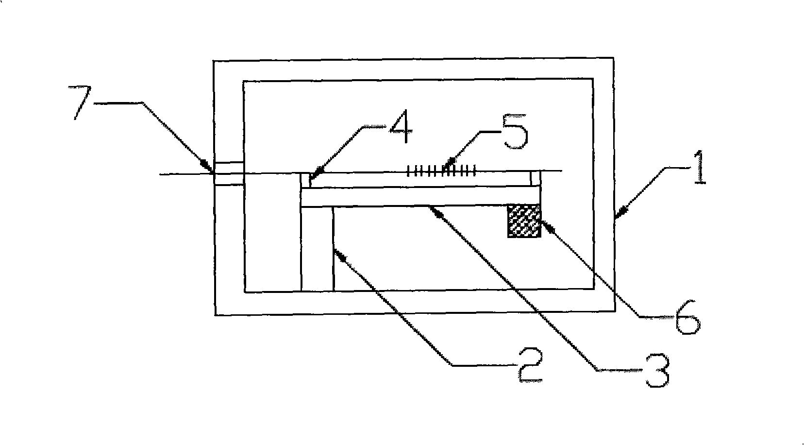
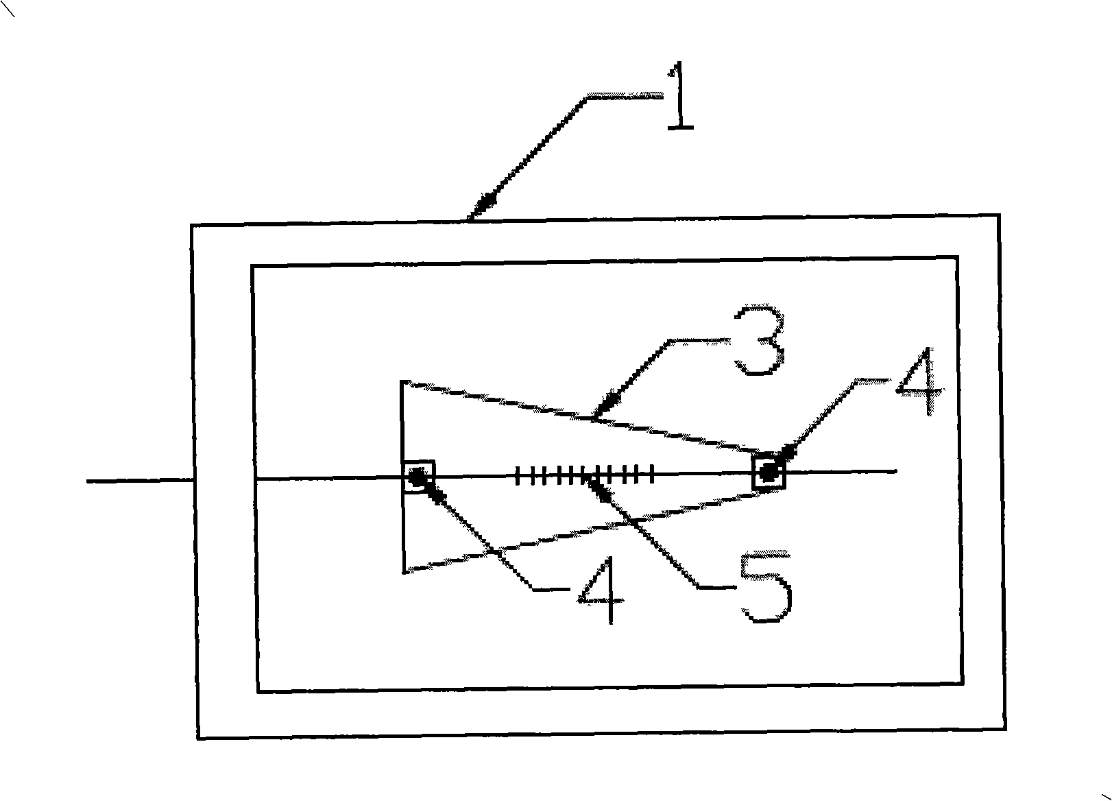
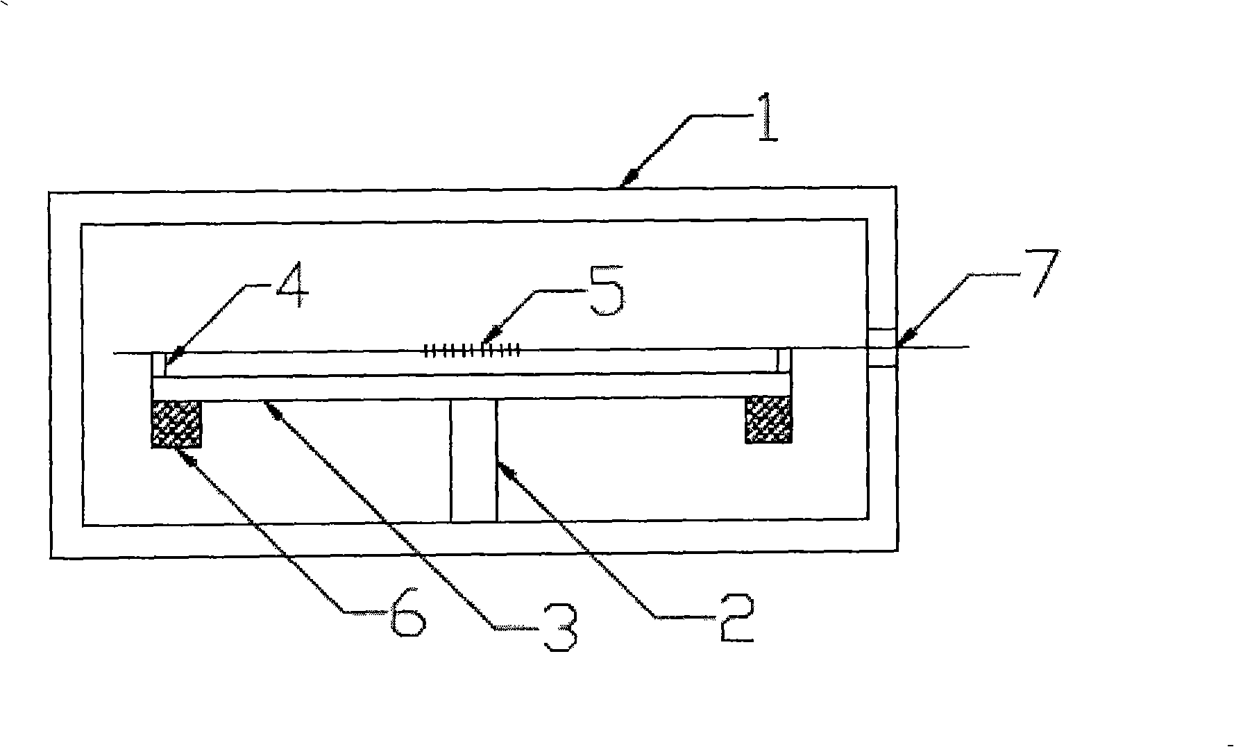
[0034] Such as figure 1 with figure 2 as shown, figure 1 It is a side view of the cantilever beam fiber grating accelerometer structure provided according to the first embodiment of the present invention, figure 2 It is a top view of the structure of the cantilever beam fiber grating accelerometer according to the first embodiment of the present invention.

[0035] from figure 1 with figure 2 It can be seen that the cantilever beam type fiber grating accelerometer includes: a housing 1 as the supporting structure of the fiber grating accelerometer; a support column 2 for fixing the cantilever beam 3, one end of the support column 2 is fixedly connected to the cantilever beam 3, and the other One end is fixedly con...


PUM


Abstract

The invention relates to the optical fiber sensor technical field, disclosing a cantilever beam-type optical fiber grating accelerometer. The accelerometer comprises an outer casing used as a support structure of the accelerometer, a support column used to fix a cantilever beam, a cantilever beam, a first lug boss and a second lug boss arranged at both ends of the upside of the cantilever beam, an optical fiber grating used to measure acceleration and a mass block arranged at one end or both end of the underside of the cantilever beam, wherein one end of the support column is fixed with the cantilever beam, while the other end is fixed with the downside surface of the accelerometer; both lug bosses are used to horizontally fix the optical fiber grating and ensures a certain space between the optical fiber grating and the cantilever beam; both ends of the optical fiber grating are respectively fixed on the first lug boss and the second lug boss on the cantilever beam with one end parallel to the surface of the cantilever beam passing through the hole on the sidewall of the accelerometer to extend outside the accelerometer; and the mass block is used to adjust the sensitivity and the natural vibration frequency of the accelerometer. The cantilever beam-type optical fiber grating accelerometer increases sensitivity and improves packaging technology.

Description

technical field [0001] The invention relates to the technical field of optical fiber sensors, in particular to a cantilever beam type optical fiber grating accelerometer. Background technique [0002] Compared with the corresponding conventional sensors, optical fiber sensors also have obvious advantages in terms of sensitivity, dynamic range, and reliability. They are particularly prominent in the fields of national defense and military applications, and are listed as key national defense technologies by many countries. [0003] Optical fiber accelerometer is an instrument that uses the light transmission characteristics of optical fiber and various modulation effects generated by its interaction with the surrounding environment to detect vibrations on the ground, in the air or on the seabed. Compared with the traditional piezoelectric accelerometer, it has the following main advantages: wide frequency range, high sound pressure sensitivity, no electromagnetic interference,...

Claims


Application Information

Patent Timeline
Patent Type & Authority Applications(China)
IPC IPC(8): G01P15/00B81B7/02
Inventor 张文涛李芳刘育梁
Owner INST OF SEMICONDUCTORS - CHINESE ACAD OF SCI
Why Eureka
Try Eureka