A fiber grating high temperature strain gauge and its calibration method

A high-temperature strain gauge and fiber grating technology, which is applied in the direction of using optical devices, instruments, measuring devices, etc., can solve the problem of inability to achieve synchronous measurement of structures, and achieve the effects of avoiding chirp phenomenon, high measurement accuracy and simple structure.

Active Publication Date: 2022-06-28
SUZHOU NUCLEAR POWER RES INST +2
View PDF13 Cites 0 Cited by
  • Summary
  • Abstract
  • Description
  • Claims
  • Application Information

AI Technical Summary

Problems solved by technology

However, the commonly used fiber grating strain sensors can only measure the strain in a single direction on the surface of the structure, and cannot realize the simultaneous measurement of the strain in multiple directions of the structure.

Method used


Image

  • A fiber grating high temperature strain gauge and its calibration method
  • A fiber grating high temperature strain gauge and its calibration method
  • A fiber grating high temperature strain gauge and its calibration method

Examples


Embodiment 1

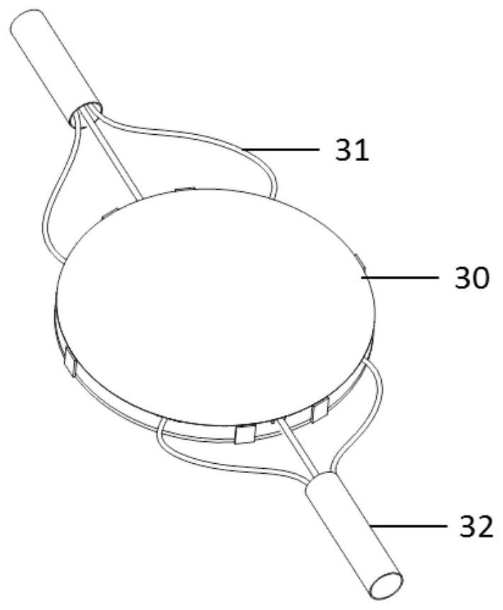
[0031] Example 1 Fiber Bragg Grating High Temperature Strain Gauge

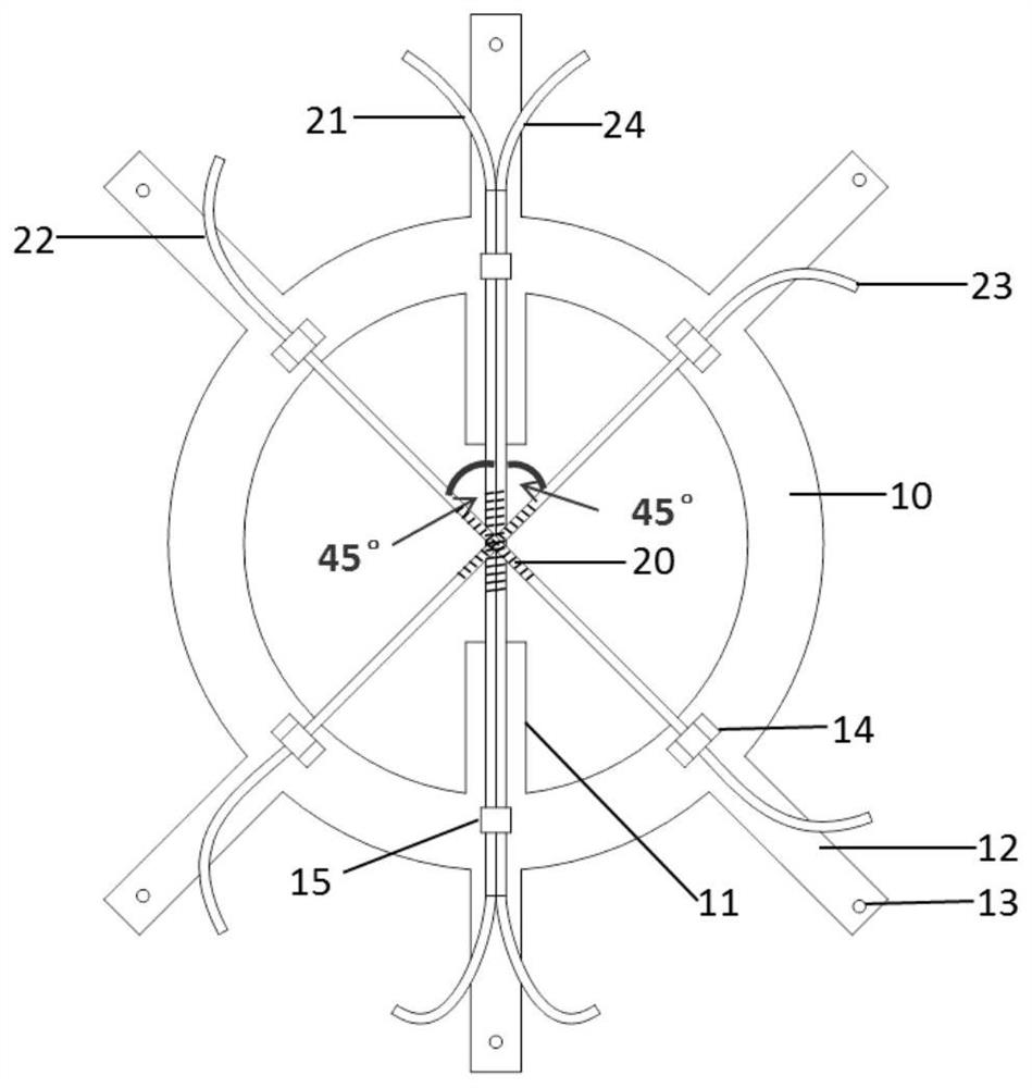
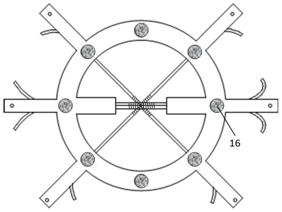
[0032] Refer to the attached image 3 , the fiber grating high-temperature strain gauge of this embodiment includes a circular ring-shaped sensor substrate 10, an optical fiber mounting arm 11, an optical fiber and a protective cover 30 arranged on the sensor substrate 10. The optical fiber mounting arm 11 is along the sensor substrate 10. The inner circumference is formed to extend inward, and the optical fibers are arranged along the diameter direction of the sensor substrate 10 . The fiber mounting arm 11 is in the same plane as the sensor substrate 10 . The size of the protective cover 30 matches the outer diameter of the sensor substrate 10. The edge of the protective cover 30 is evenly spaced with connecting parts. The protective cover 30 is connected with the sensor substrate 10 through the connecting parts to protect the optical fiber. The protective cover 30 is Metal Material.

[0033] The stiffne...

Embodiment 2

[0044] Embodiment 2 Calibration method

[0045] Based on the strain gauge in Example 1, the calibration method in this example is performed according to the following steps:

[0046] 1) Fix the two stretching devices corresponding to both ends of the first optical fiber on the stress sensor calibration platform through the stretching circular hole;

[0047] 2) The tensile displacement is obtained by the tensile displacement method as ΔL i When , the wavelength shift of the first fiber Δλ i , where i=1,2,3,...,n;

[0048] 3) Measure the length L between the two fixed ends of the first fiber, and calculate the strain ε of the strain gauge in the direction of the first fiber i =ΔL i / L(i=1,2,...,n);

[0049] 4) Put several pairs of measurement points (Δλ i , ε i ) for linear fitting, and the slope K of the fitted line 1 is the strain sensitivity of the strain gauge in the direction of the first fiber;

[0050] 5) Repeat steps 1) to 4) for the second optical fiber and the...


PUM

PropertyMeasurementUnit
thicknessaaaaaaaaaa
heightaaaaaaaaaa
heightaaaaaaaaaa

Abstract

The invention discloses a fiber grating high-temperature strain gauge, which comprises a sensor substrate, an optical fiber installation arm and an optical fiber arranged on the sensor substrate, the sensor substrate is circular, and the optical fiber installation arm is arranged along the The inner circumference of the sensor substrate extends inwardly, and the optical fiber is arranged along the diameter direction of the sensor substrate; the optical fiber includes a temperature optical fiber for only sensing temperature; the sensor substrate is provided with different heights The boss is used to fix the optical fiber, and the boss is used to avoid cross contact between different optical fibers. The fiber grating high-temperature strain gauge of the present invention eliminates the influence of temperature on strain measurement; the boss design on the sensor substrate can effectively avoid the chirp phenomenon caused by the cross contact of FBG optical fibers; the strain gauge has simple structure and multi-directional strain synchronization With the advantages of measurement, temperature compensation, and high measurement accuracy, it can be used for simultaneous measurement of multi-directional strain on the surface of structures.

Description

technical field [0001] The invention belongs to the field of structural strain measurement and sensor design, in particular to a fiber grating high temperature strain gauge and a calibration method for the strain gauge. Background technique [0002] Strain is one of the important parameters in structural health monitoring, which can effectively reflect the internal force of the structure. The commonly used strain measurement method is the resistance strain gauge measurement method, but for the strain measurement in the high temperature, humidity and strong electromagnetic interference environment, there are many problems such as long glue curing time, degumming of the edge of the strain gauge, serious electromagnetic interference, zero drift, strain gauge corrosion, etc. Problems such as abnormal measurement signals. At the same time, resistance strain gauges in high temperature environments have a short service life and low installation survival rate, making it difficult t...

Claims


Application Information

Patent Timeline
Patent Type & Authority Patents(China)
IPC IPC(8): G01B11/16
CPCG01B11/16
Inventor 王红珂徐德城陈潇林磊张国栋薛飞
Owner SUZHOU NUCLEAR POWER RES INST
Why Eureka
Try Eureka