Broad-band piezoelectricity oscillating generating set

A piezoelectric power generation, broadband technology, applied in generators/motors, piezoelectric effect/electrostrictive or magnetostrictive motors, electrical components, etc. To achieve the effect of maximizing power generation efficiency

Inactive Publication Date: 2008-09-24
INST OF ELECTRICAL ENG CHINESE ACAD OF SCI
View PDF4 Cites 54 Cited by
  • Summary
  • Abstract
  • Description
  • Claims
  • Application Information

AI Technical Summary

Problems solved by technology

[0006] The purpose of the present invention is to overcome the shortcomings of current piezoelectric vibration power generation technology such as single working mo

Method used


Image

  • Broad-band piezoelectricity oscillating generating set
  • Broad-band piezoelectricity oscillating generating set
  • Broad-band piezoelectricity oscillating generating set

Examples


Embodiment Construction

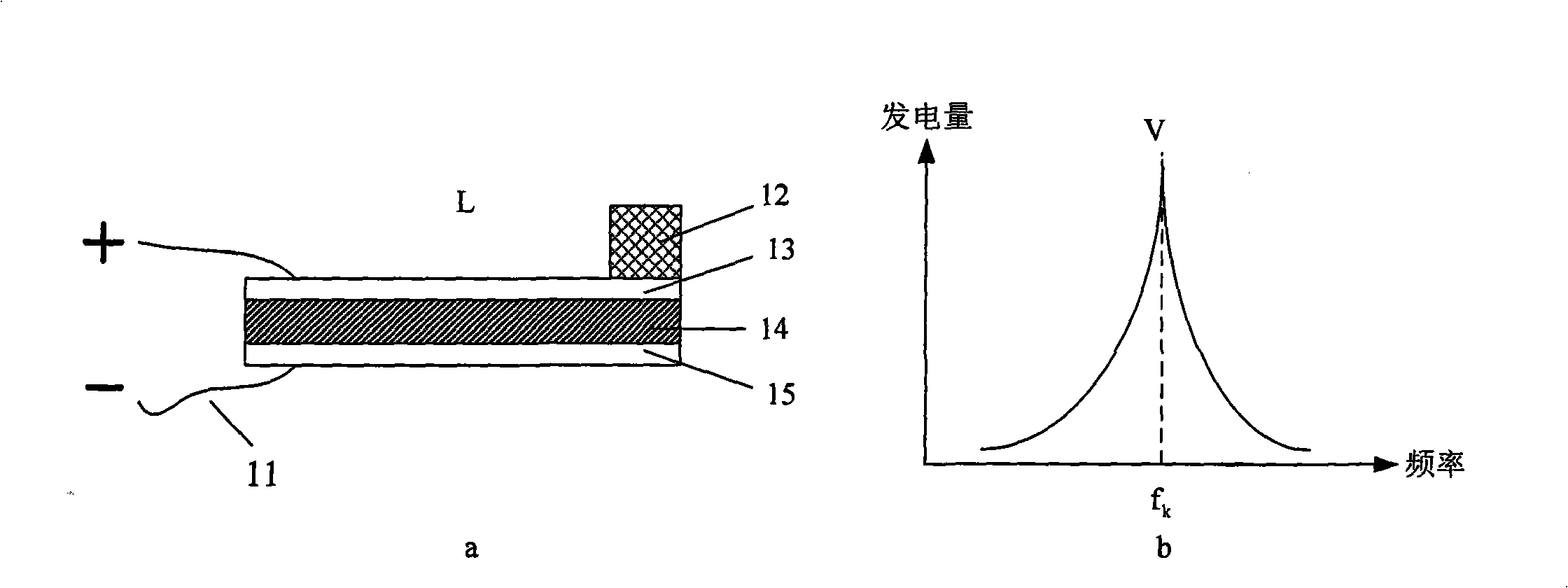
[0018] figure 1 a describes the structure of the prior art single cantilever beam L, the single cantilever beam L includes a piezoelectric transducing element 14, a lead wire 11, a metal block 12, a positive electrode 13 and a negative electrode 15, the piezoelectric transducing element 14 and two electrodes 13 and 15 are stacked and arranged, and the piezoelectric transducer element 14 is located between the positive electrode 13 and the negative electrode 15, similar to a sandwich structure. The lead wire 11 is located at the fixed end of the cantilever beam L, and is used to derive positive and negative charges respectively, and the metal block 12 is located at the free end of the cantilever beam L, so that the single cantilever beam L can generate the maximum amplitude when vibrating. figure 1 b for figure 1 The power generation-frequency curve of a single cantilever beam shown in a, the horizontal axis represents the frequency of external vibration, and the vertical axis...


PUM


Abstract

The invention relates to a board band piezoelectric generating set. A plurality of socle beams L1, L2, L3 are divided into two groups; one end of each socle beam is fixed and the other end keeps free; the socle beams keep parallel with each other; a crossing section is arranged between the two groups of the socle beams; wherein, the socle beam consists of piezoelectric transduction elements (34, 36), a down-lead (31), a metal block (32) and electrodes (33, 35, 37). The electrodes and the transduction elements are alternately arranged; the down-lead (31) is arranged at the fixed end of the socle beam; the metal block (32) is arranged at the free end of the socle beam. The sizes and the structures of the socle beams L1, L2, L3 are different, the manufacture materials of the piezoelectric transduction elements are different and the qualities of the metal blocks are different, therefore, the resonance frequency of each beam is different. The two groups of the socle beams L1, L2, L3 are arranged in an interdigital structure in plane or an interdigital structure in space. The board band piezoelectric generating set can absorb the mechanical vibration or noise of a plurality of frequency components in the environment and realize the transformation from mechanical energy to electricity energy by the piezoelectric transduction elements so as to increase the generating capacity and improve the generating efficiency.

Description

technical field [0001] The present invention relates to a piezoelectric vibration power generation device. Background technique [0002] In recent years, fossil energy has gradually become scarce, and the resulting energy crisis has gradually begun to affect economic development and people's lives. Under the pressure of energy and environmental protection, people have gradually begun to explore the use of new energy sources, and converting the ubiquitous vibrations in the natural environment into electrical energy is one of them. The piezoelectric effect of piezoelectric materials (mechanical energy Electric energy) provides the possibility to use mechanical vibration to generate electricity. [0003] With the development of micro-electromechanical systems (MEMS) and microelectronics technology, various electronic products with micro-power consumption are gradually coming out, which objectively promotes the research of micro-energy (Micro Power, generally in the order of ...

Claims


Application Information

Patent Timeline
IPC IPC(8): H02N2/18
Inventor 姜楠刘俊标
Owner INST OF ELECTRICAL ENG CHINESE ACAD OF SCI
Why Eureka
Try Eureka