Experimental device for vortex-induced vibration piezoelectric energy harvester in water flow and use method of experimental device

A piezoelectric energy capture and vortex-induced vibration technology, which is used in measurement devices, piezoelectric effect/electrostrictive or magnetostrictive motors, instruments, etc. Complex modeling and calculation problems

Active Publication Date: 2019-05-24
BEIJING UNIV OF TECH
View PDF15 Cites 8 Cited by
  • Summary
  • Abstract
  • Description
  • Claims
  • Application Information

AI Technical Summary

Problems solved by technology

[0006] In 2004, pobering et al. used piezoelectric materials to make a piezoelectric power generation flag suitable for low-velocity water flow. Using the Karman vortex street generated by the principle of vortex-induced vibration, the power generation flag was bent to obtain electric energy. This device was placed in the river, and the water flow Electricity is generated when flowing through the device, but the energy conversion efficiency is low
However, the invention does not provide relevant experimental devices and experimental methods, and the design of the piezoelectric energy harvester is single, unable to adapt to various flow velocity environments, and unable to adjust experimental parameters, so it can only be applied to wind tunnel tests
[0009] The mechanism of vortex-induced vibration is very complicated, and for the vortex-induced vibration mechanism of piezoelectric energy harvesters in water flow, due to the effect of fluid-solid coupling, theoretical modeling calculations become more complicated

Method used


Image

  • Experimental device for vortex-induced vibration piezoelectric energy harvester in water flow and use method of experimental device
  • Experimental device for vortex-induced vibration piezoelectric energy harvester in water flow and use method of experimental device
  • Experimental device for vortex-induced vibration piezoelectric energy harvester in water flow and use method of experimental device

Examples


Embodiment

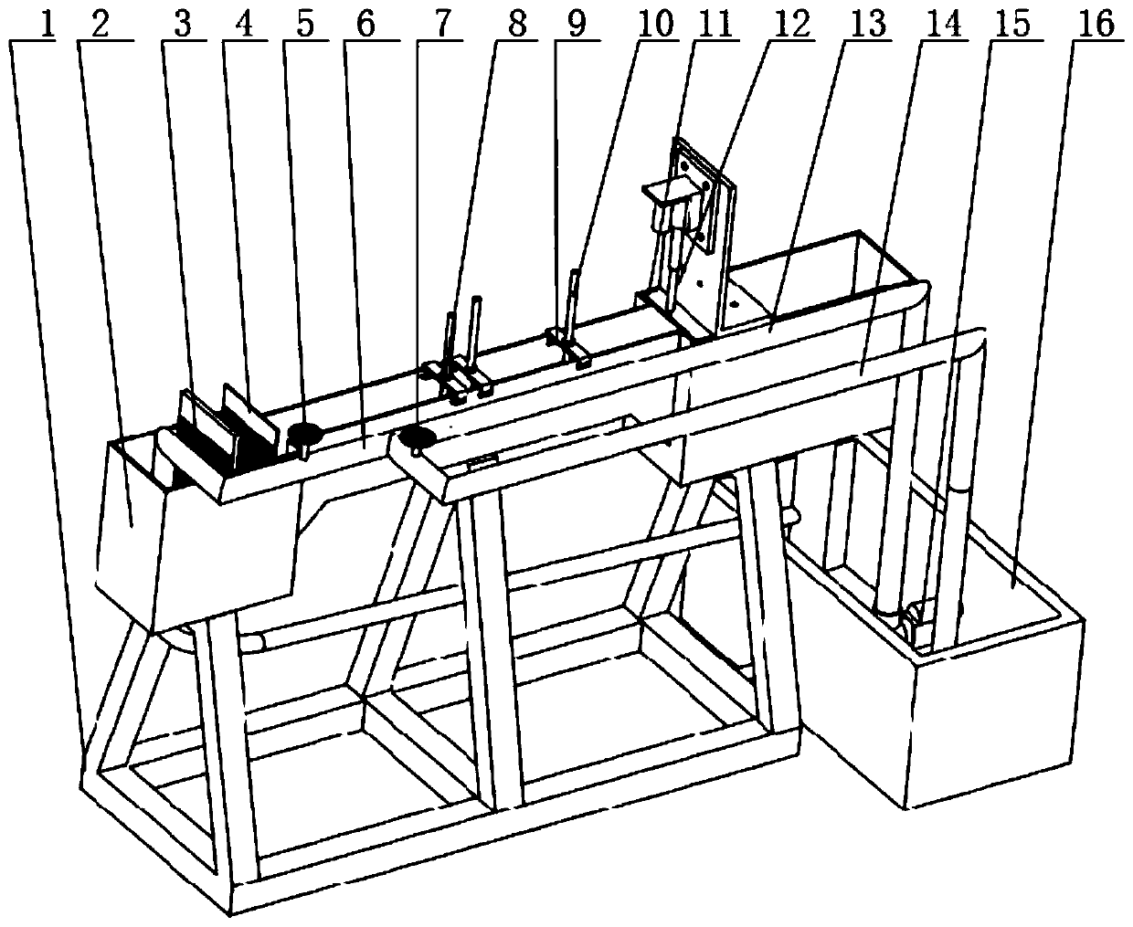
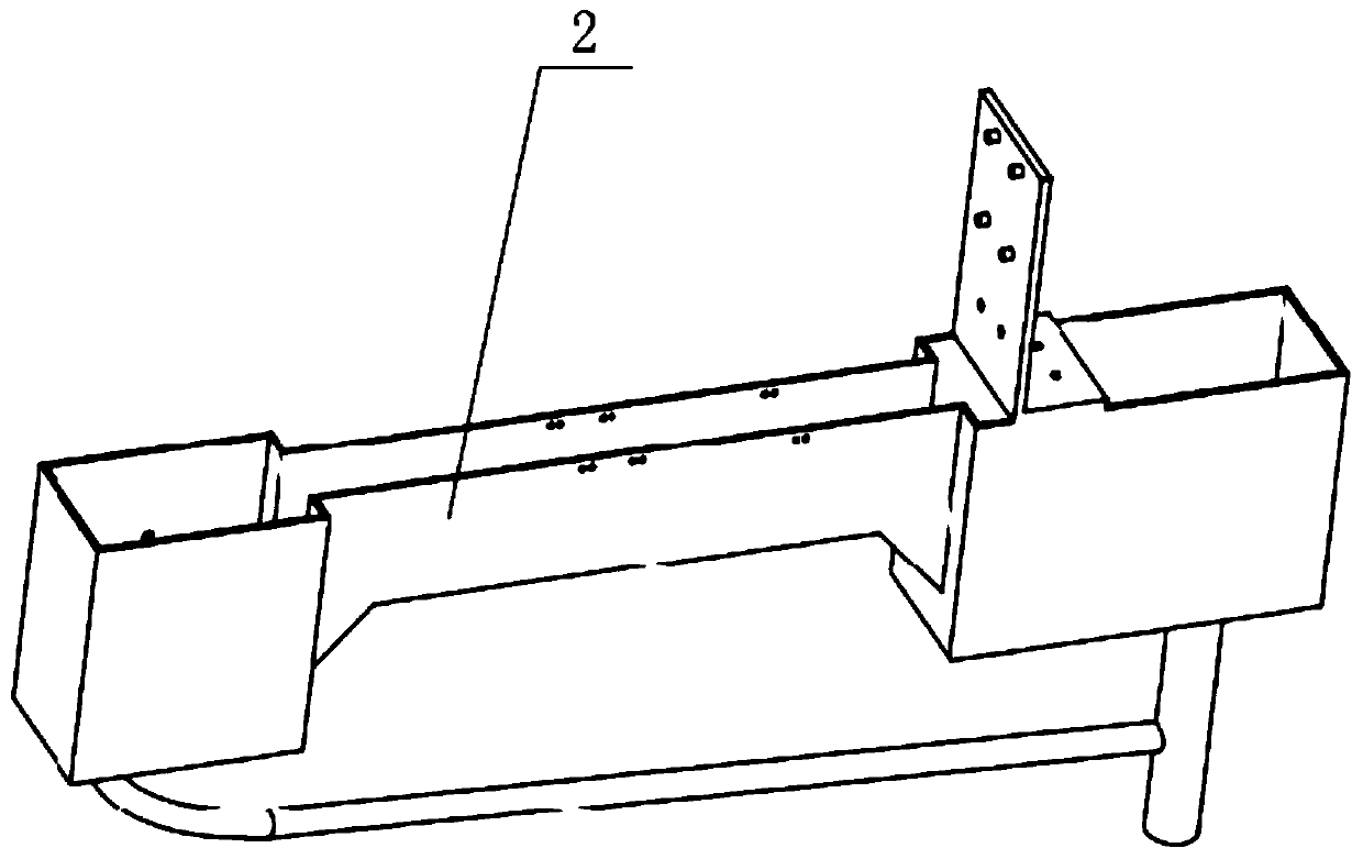
[0071] Example: such as Figure 1 to Figure 3 As shown, the experimental device of the vortex-induced vibration piezoelectric energy harvester in the water flow, the experimental device includes the experimental platform and the piezoelectric energy harvesting device used in the experiment. Described experimental platform comprises: water intake area, experiment area and drainage area, water tank (2) is positioned and installed on the water tank support (1) by bolt, honeycomb device (3) and damping net (3) pass through the groove on the tank wall The groove positioning is installed in the water tank (2), and the drain baffle (11) is installed in the water tank (2) by the groove positioning on the water tank wall equally. The DC push rod motor (12) is positioned and installed on the tank cover by screws, and the push rod end of the DC push rod motor (12) and the drain baffle (11) are connected by a coupling to ensure that the drain baffle (11) can With the telescopic movement ...


PUM


Abstract

The invention discloses an experimental device for a vortex-induced vibration piezoelectric energy harvester in water flow and a use method of the experimental device. The experimental device comprises an experimental platform and experimental piezoelectric energy harvesting devices. The experimental platform comprises a water tank support, a water tank, a honeycomb, a damping net, a drainage baffle plate, a water inlet pipe, a water return pipe and the like. The water flow sequentially flows a water inlet area, an experimental area and a drainage area from left to right, and the flow velocityof the water flow in the water tank can be adjusted by the aid of a water inlet valve, a water return valve and the drainage baffle plate to obtain a stable laminar flow field environment. Accordingto the piezoelectric energy harvesting devices, excited permanent magnets are embedded into flow around circular cylinders to introduce nonlinear magnetic force, resonance bandwidth, namely resonanceflow velocity range can be effectively extended, resonance can be generated within different flow velocity ranges, and experimental exploration requirements are met. A low-flow-velocity stable laminarflow field can be effectively simulated, the flow velocity is accurately adjusted, and various experimental data can be measured at different flow velocities by the aid of the energy harvesting devices with various structures.

Description

technical field [0001] The invention relates to an experimental device for vortex-induced vibration of a cylinder surrounding a fluid in a water flow and a method for using it, in particular to an experimental device for a piezoelectric energy harvester vortex-induced vibration that introduces a nonlinear magnetic force by embedding a permanent magnet in the fluid surrounding a cylinder and how to use it. Background technique [0002] With the sustained and rapid development of the economy and society, the demand for energy is increasing day by day, and non-renewable energy sources such as coal and oil are becoming exhausted, so it is essential to seek new energy sources and utilize renewable energy sources. As a renewable energy source in the environment, hydropower is abundant in reserves. In the face of high-speed water flow environment, hydropower stations can be built to use turbines to convert the kinetic energy of water flow into electrical energy, but the turbines h...

Claims


Application Information

Patent Timeline
Patent Type & Authority Applications(China)
IPC IPC(8): G01R29/22H02N2/18
Inventor 曹东兴丁相栋
Owner BEIJING UNIV OF TECH
Why Eureka
Try Eureka