Variable valve timing control apparatus for internal combustion engine

a control apparatus and valve timing technology, applied in mechanical equipment, valve arrangements, machines/engines, etc., can solve the problems of pin deformation, difficult to maintain the vct phase close to a predetermined value, and the vct phase may not become securely locked, etc., to achieve the effect of rapid and smooth operation

Active Publication Date: 2010-10-28
DENSO CORP
View PDF14 Cites 50 Cited by
  • Summary
  • Abstract
  • Description
  • Claims
  • Application Information

AI Technical Summary

Benefits of technology

The invention prevents ooil leaks while an engine is running at idle. This ensures that there will always be enough oil available for quick acceleration, which could otherwise cause issues because of lack of lubricant.

Problems solved by technology

The technical problem addressed in this patent is how to improve the stability and responsiveness of a variable valve tim mechanism used in engines equipped with a hydraulic system. More specifically, the issue relates to the difficulty of ensuring the proper locking of the vapor timing without experiencing issues like incomplete engagement or excessive loads on components, resulting in delay in identifying the optimal time points for lock releasing, and poor detection of the lock release operation. Additionally, controlling the amount of oil pressure in relation to holding the desired target phase requires careful consideration, but doing so that may negatively impact fuel economy and idle speed.

Method used


Image

  • Variable valve timing control apparatus for internal combustion engine
  • Variable valve timing control apparatus for internal combustion engine
  • Variable valve timing control apparatus for internal combustion engine

Examples


Embodiment Construction

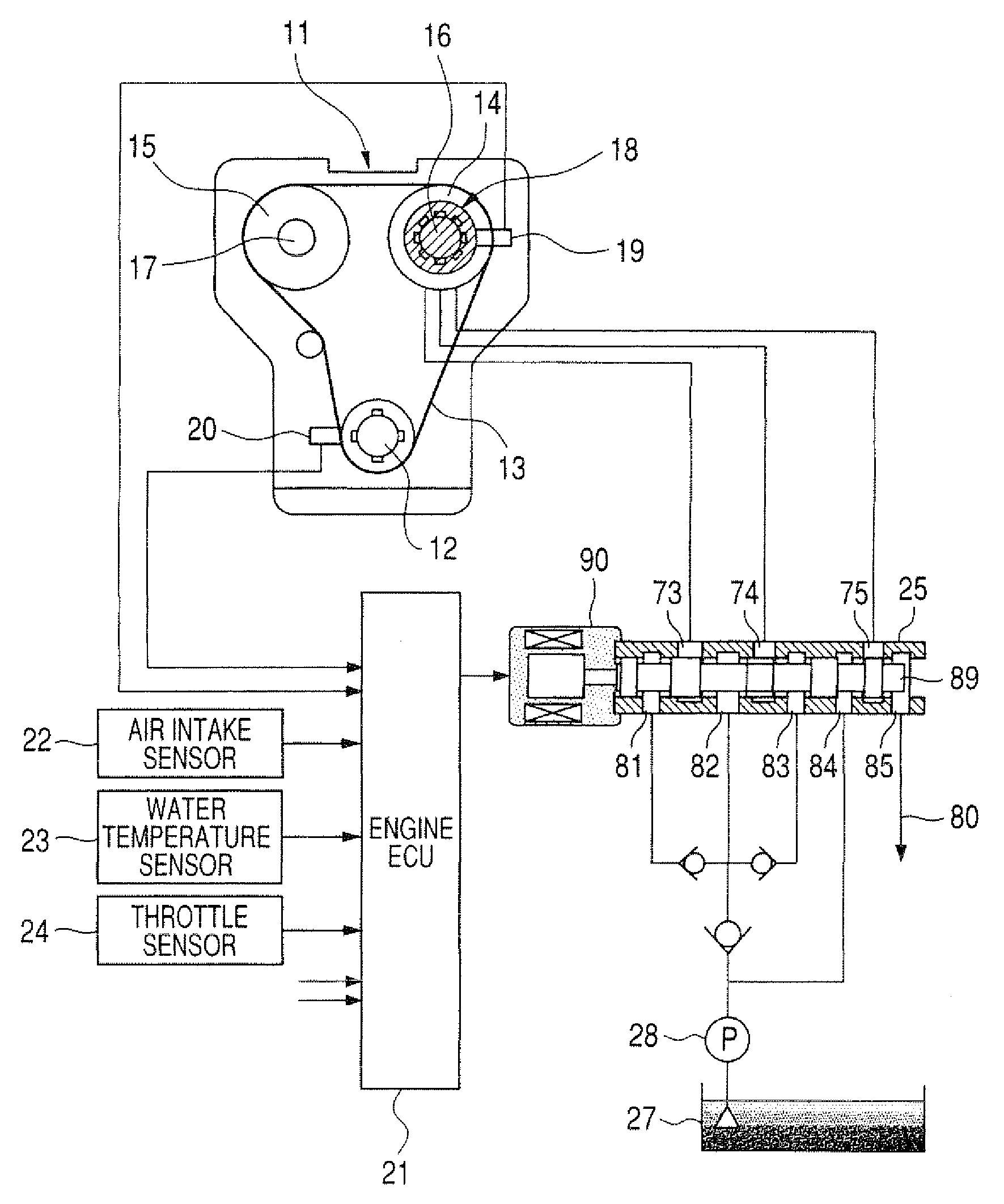
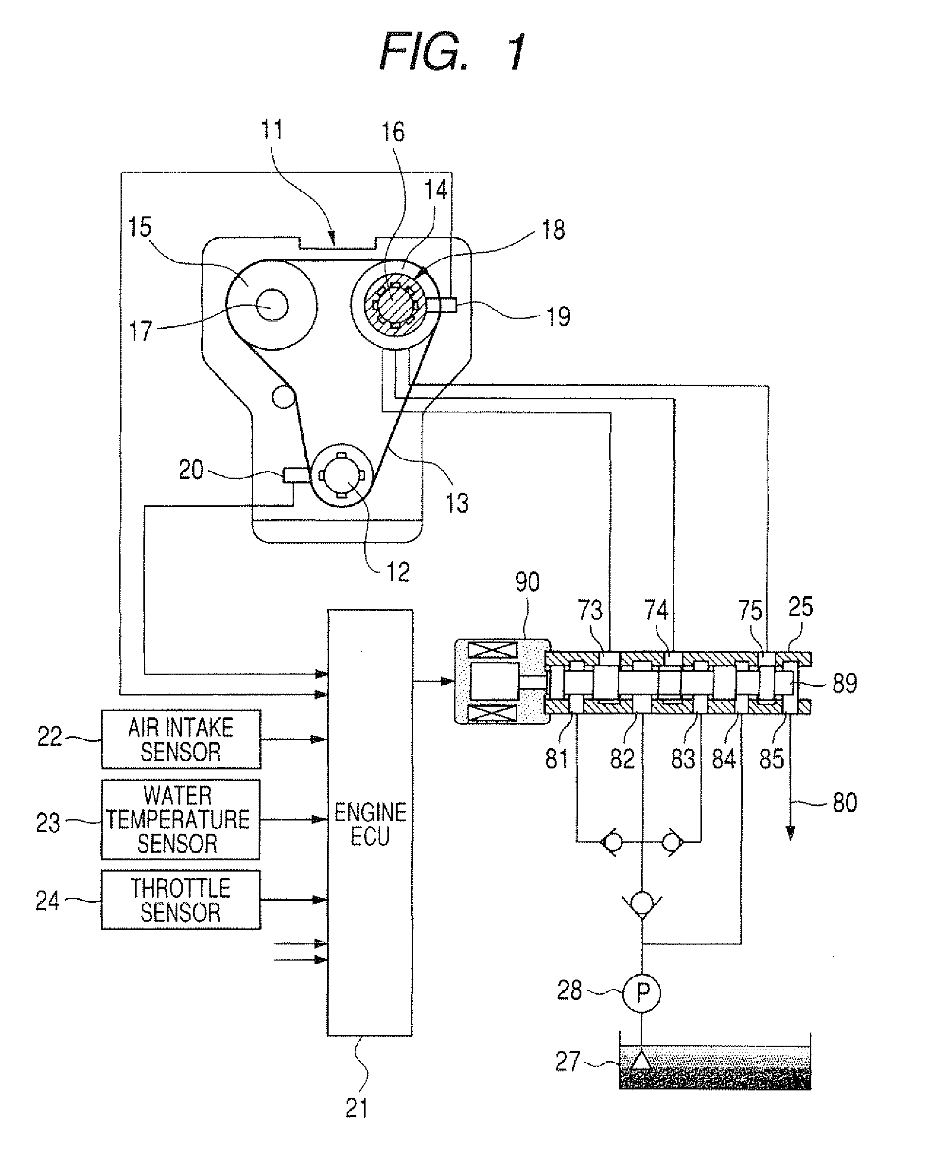
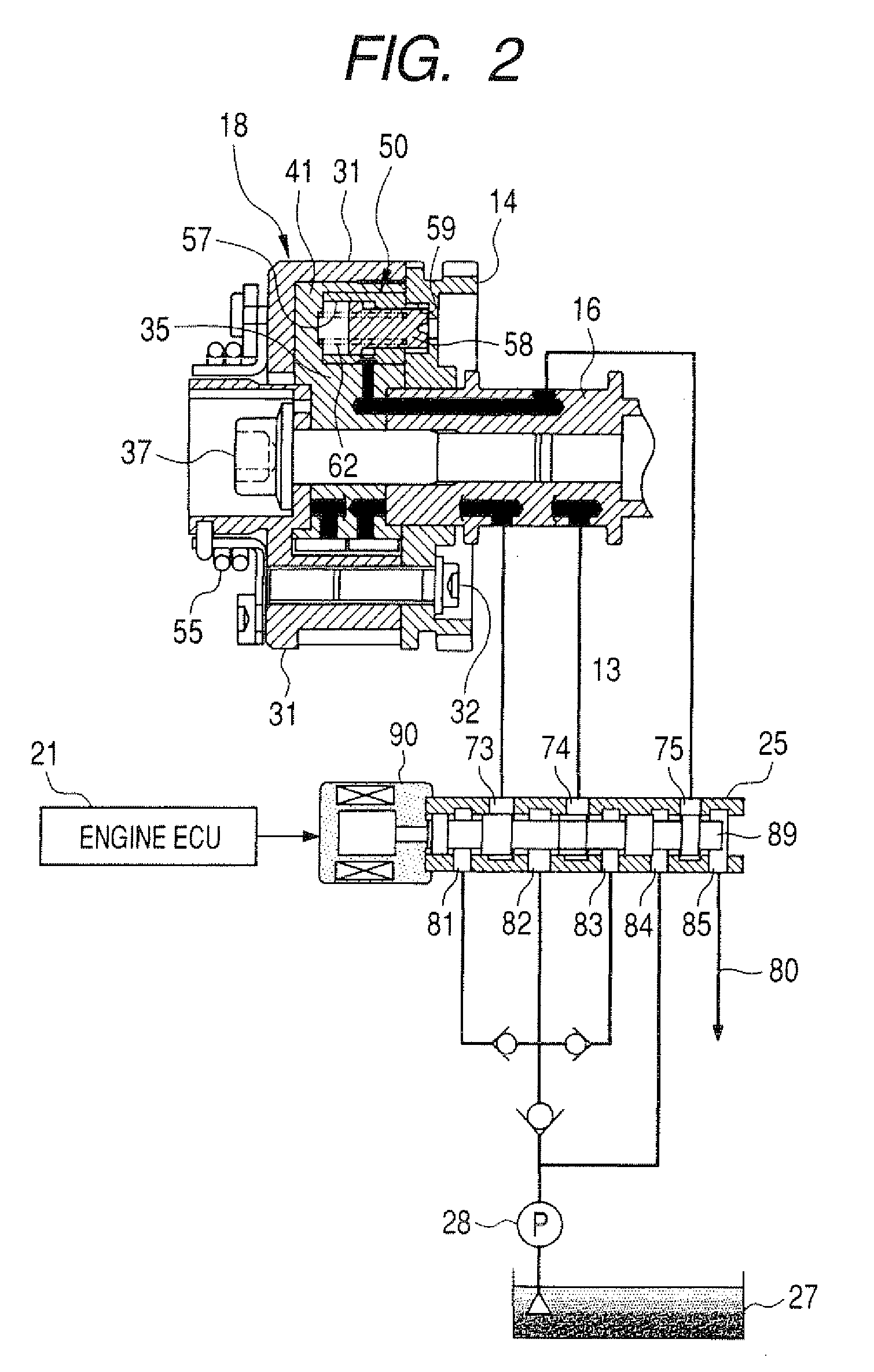
[0055]An embodiment of a variable valve timing control apparatus is described in the following, referring first to FIG. 1. The embodiment is a combination of a variable valve timing apparatus 18, which is a hydraulic drive mechanism that is JO supplied with oil under pressure from an hydraulic control valve 25, and control functions which are implemented by an engine ECU (electronic control unit) 21 for controlling the variable valve timing apparatus 18, by varying the duty ratio of drive pulses supplied to operate a solenoid 90 which actuates the hydraulic control valve 25. Motive force from the crankshaft 12 of an engine 11 is transmitted by a timing chain 13 via sprockets 14 and 15 respectively of an intake camshaft 16 and an exhaust camshaft 17, so that the intake camshaft 16 (camshaft which actuates the air intake valves of the engine 11) rotates in synchronism with the crankshaft 12. The intake camshaft 16 is provided with the variable valve timing apparatus 18, which is contr...


PUM


Abstract

A variable valve timing control apparatus adjusts the rotation phase (VCT phase) of an engine camshaft by selectively supplying oil to an advancement chamber and a retardation chamber, and includes a lock pin which is controlled for being moveable to a first position, in which the rotation phase is adjustable, and a second position, in which the camshaft is locked at a specific rotation phase. When the lock pin is displaced from the first position, oil becomes enabled to pass between the advancement chamber and retardation chamber, to thereby enabling the rotation phase to be changed to the specific rotation phase by supplying oil to an appropriate one of the advancement chamber and a retardation chamber, for initiating locking.

Description


Claims


Application Information

Patent Timeline
Owner DENSO CORP
Why Eureka
Try Eureka