
Eureka
For R&D, Eureka makes reading and utilizing patents & technical documents easy.
Eureka AIR
Designed for self-driven R&D workflows. Generate viable solutions, solve complex R&D challenges, empower your innovation with AI.

Eureka Materials
Designed for material experts only. Revolutionize your material R&D, from search, analyze, to developing new materials.

TechResearch
Generate reliable direction feasibility study reports for your R&D in just a few steps.

TechSeek
Discover and master advanced knowledge NOW. Basics, ideas, possibilities, all at once.

TechMind
As an expert in R&D Theories, TechMind can generates customized viable solutions instantly.

TechRisk
Analyze your overall solution with one click, know your potential R&D risks in advance.

TechMonitor
Get weekly tech updates, stay abreast of the latest tech innovations and key insights.
Integral rotor noise attenuators
- Summary
- Abstract
- Description
- Claims
- Application Information
AI Technical Summary
Problems solved by technology
Method used
Image

Examples
Embodiment Construction
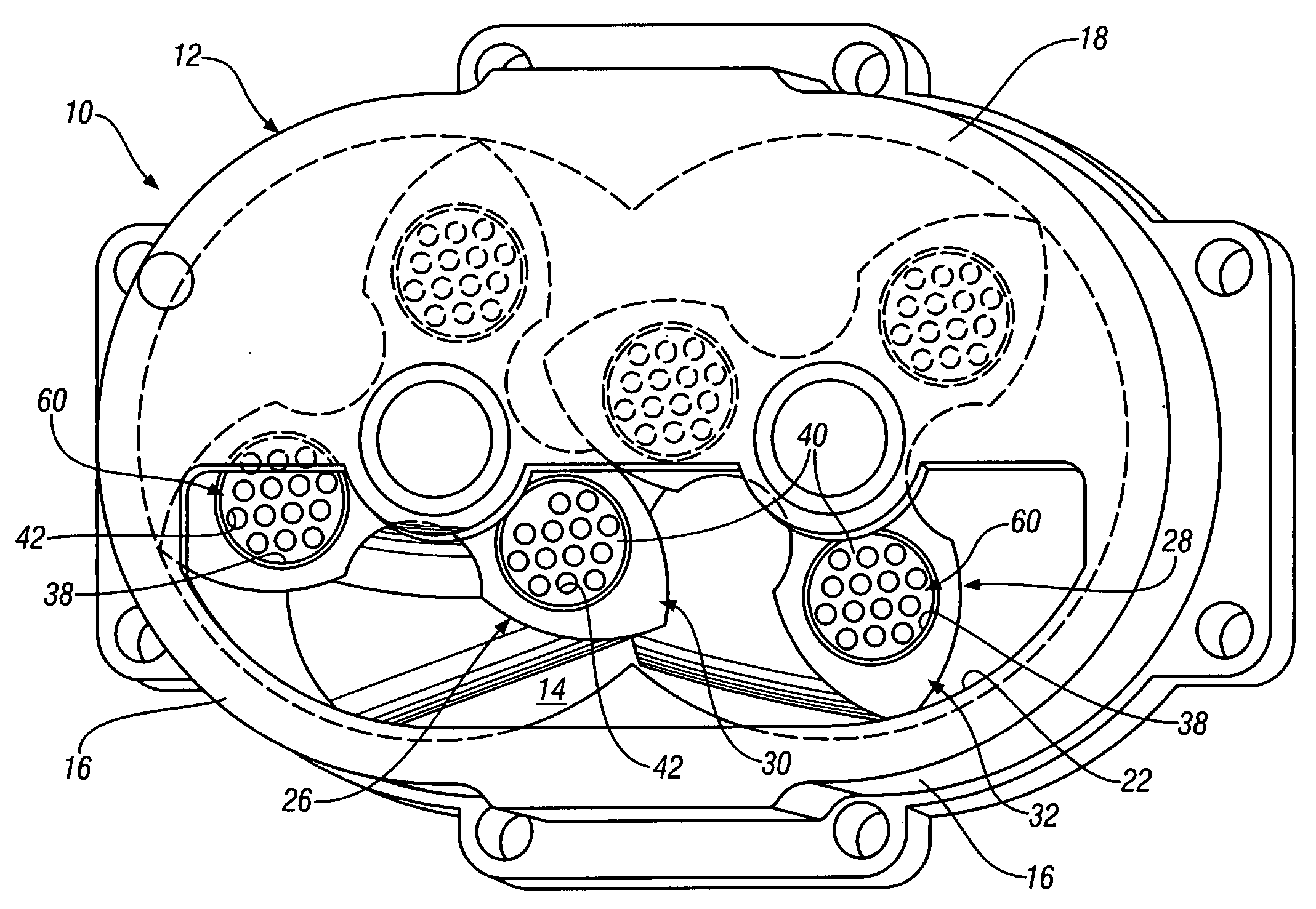
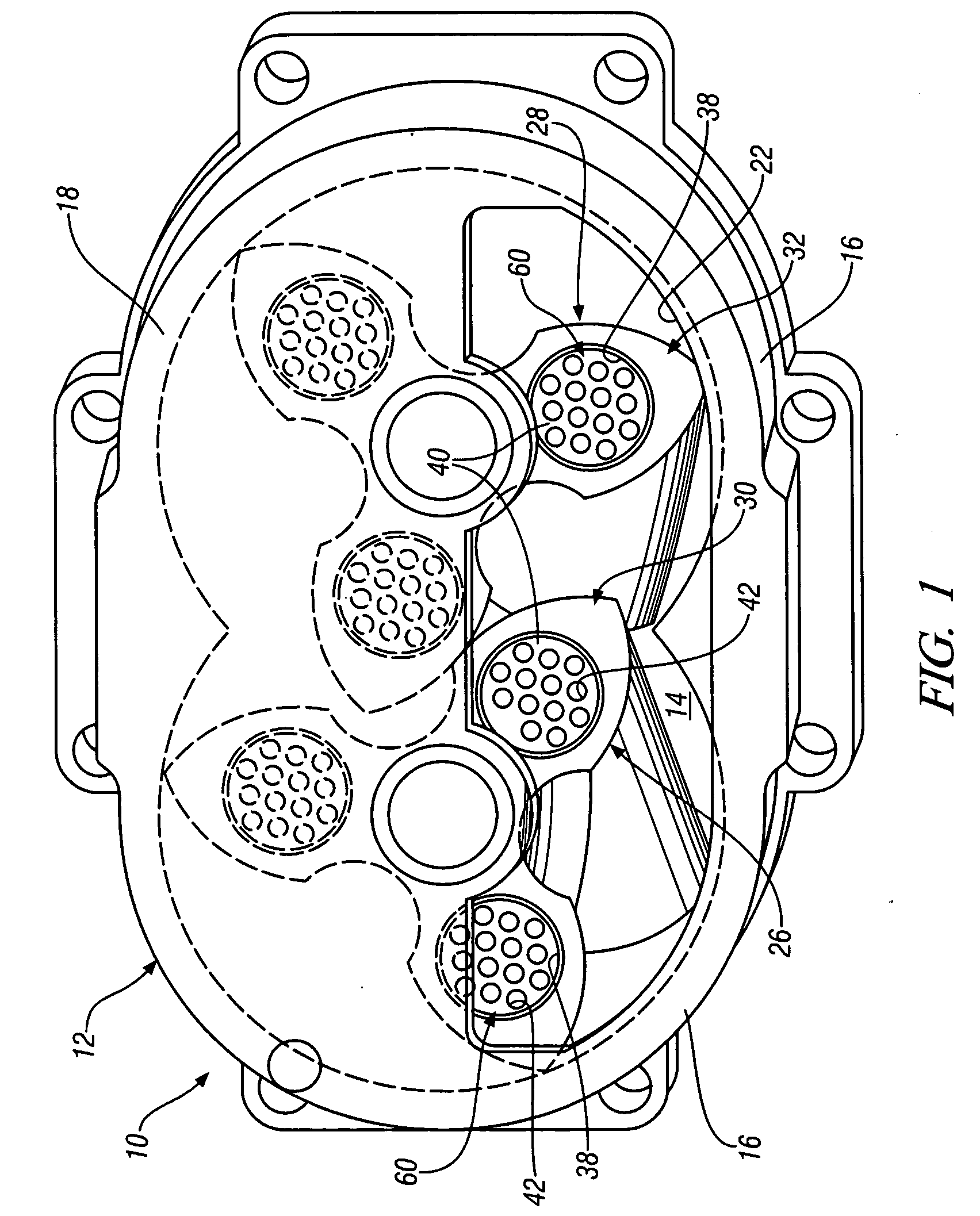
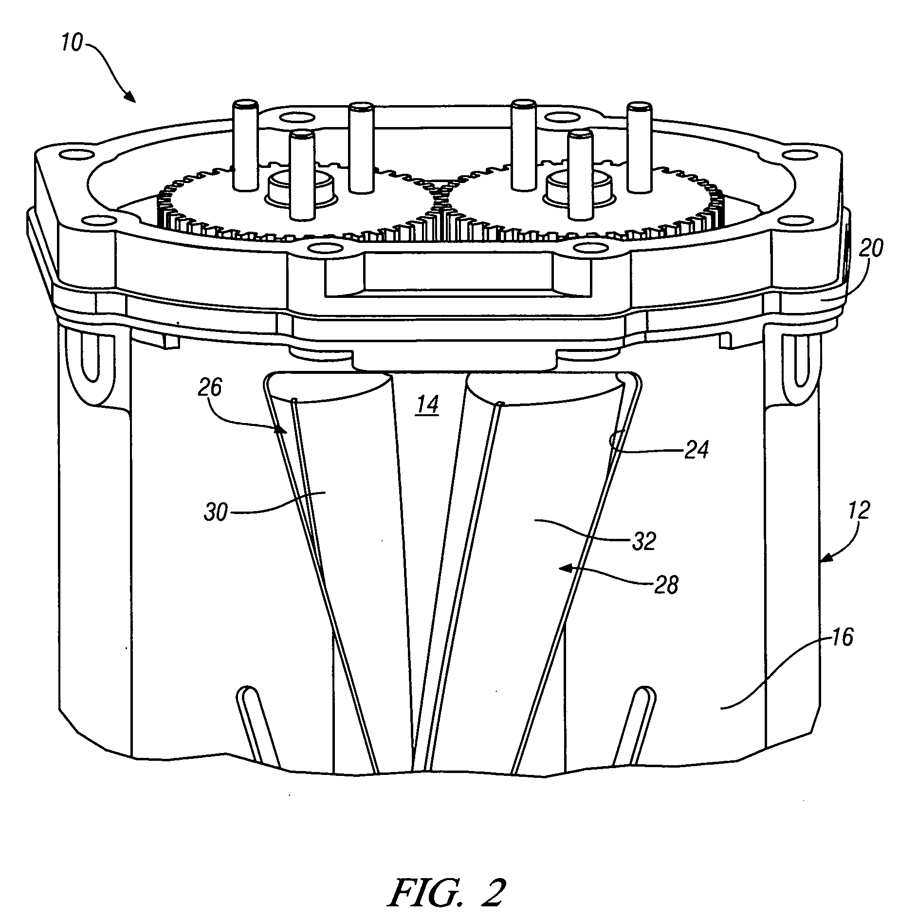
[0016]In accordance with an exemplary embodiment of the present invention FIGS. 1 and 2 illustrate a positive displacement, helical lobed supercharger 10 (Roots-type supercharger) according to the invention. Supercharger 10 includes a housing 12 having an internal cavity 14 defined by a surrounding wall 16 and upstream and downstream end walls 18, 20, respectively. An inlet opening 22 in a lower portion of the upstream end wall 18 fluidly communicates the internal cavity 14 with a source of inlet air from an air intake system (not shown). An outlet opening 24 extends through the surrounding wall 16, adjacent the downstream end wall 20 of the housing, and communicates the cavity 14 with a pressure charging air system of the engine intake system (not shown).
[0017]Within the internal cavity 14 there are rotatably mounted a pair of supercharger rotors 26, 28, each having a plurality of lobes 30, 32 with opposite helix angles, the details of which are shown in FIG. 3. The lobes 30, 32 of...
PUM
 Abstract
Description
Claims
Application Information
 - R&D Engineer
- R&D Manager
- IP Professional
- Industry Leading Data Capabilities
- Powerful AI technology
- Patent DNA Extraction
Browse by: Latest US Patents, China's latest patents, Technical Efficacy Thesaurus, Application Domain, Technology Topic, Popular Technical Reports.
© 2024 PatSnap. All rights reserved.Legal|Privacy policy|Modern Slavery Act Transparency Statement|Sitemap|About US| Contact US: help@patsnap.com