Virtual Links in a Routed Ethernet Mesh Network

a virtual link and ethernet mesh technology, applied in data switching networks, digital transmission, electrical equipment, etc., can solve the problems of persistent congestion, over-utilization of links that were not non-utilization of links that weren't part of the spanning tree, so as to achieve the same cost metric and broad spectrum of traffic manipulation

Active Publication Date: 2010-10-28
CIENA
View PDF6 Cites 101 Cited by
  • Summary
  • Abstract
  • Description
  • Claims
  • Application Information

AI Technical Summary

Benefits of technology

[0006]Virtual links may be used to divert traffic within an Ethernet network. The virtual link may be advertised with its own cost metric or may be advertised to have the same cost metric as the current shortest path between its end nodes. In one embodiment, the virtual link may be established on the network via a routing system in use on the network. Nodes on a defined path for the virtual link will install forwarding state for the virtual link so that traffic may follow the defined path through the network. Where the virtual link is advertised to have the same cost metric as the current shortest path between the end nodes, inclusion of the virtual link, from a routing perspective, will not affect other traffic patterns on the network. In this embodiment, once established, the end nodes on the virtual path will have two equal cost paths through the network—one following the shortest path tree and one along the path for the virtual link. The end nodes may use a tie breaking process in an Equal Cost Multi Path (ECMP) selection process to preferentially select the virtual link over the shortest path. Placement of the virtual link endpoints, control of metric assignment and control over what multipath permutations the link applies to permits a broad spectrum of traffic manipulation to be supported.

Problems solved by technology

This often led to over-utilization of the links that were on the spanning tree and non-utilization of the links that weren't part of the spanning tree.
This means that any mismatch between offered load and physical network build can result in persistent congestion.
When congestion occurs on the network, traffic will be dropped in transit and will need to be re-sent or, where resending is not possible due to application constraints, the application itself is degraded.

Method used


Image

  • Virtual Links in a Routed Ethernet Mesh Network
  • Virtual Links in a Routed Ethernet Mesh Network
  • Virtual Links in a Routed Ethernet Mesh Network

Examples


Embodiment Construction

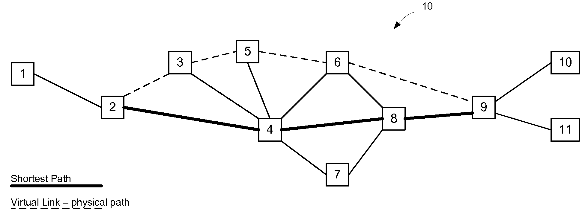
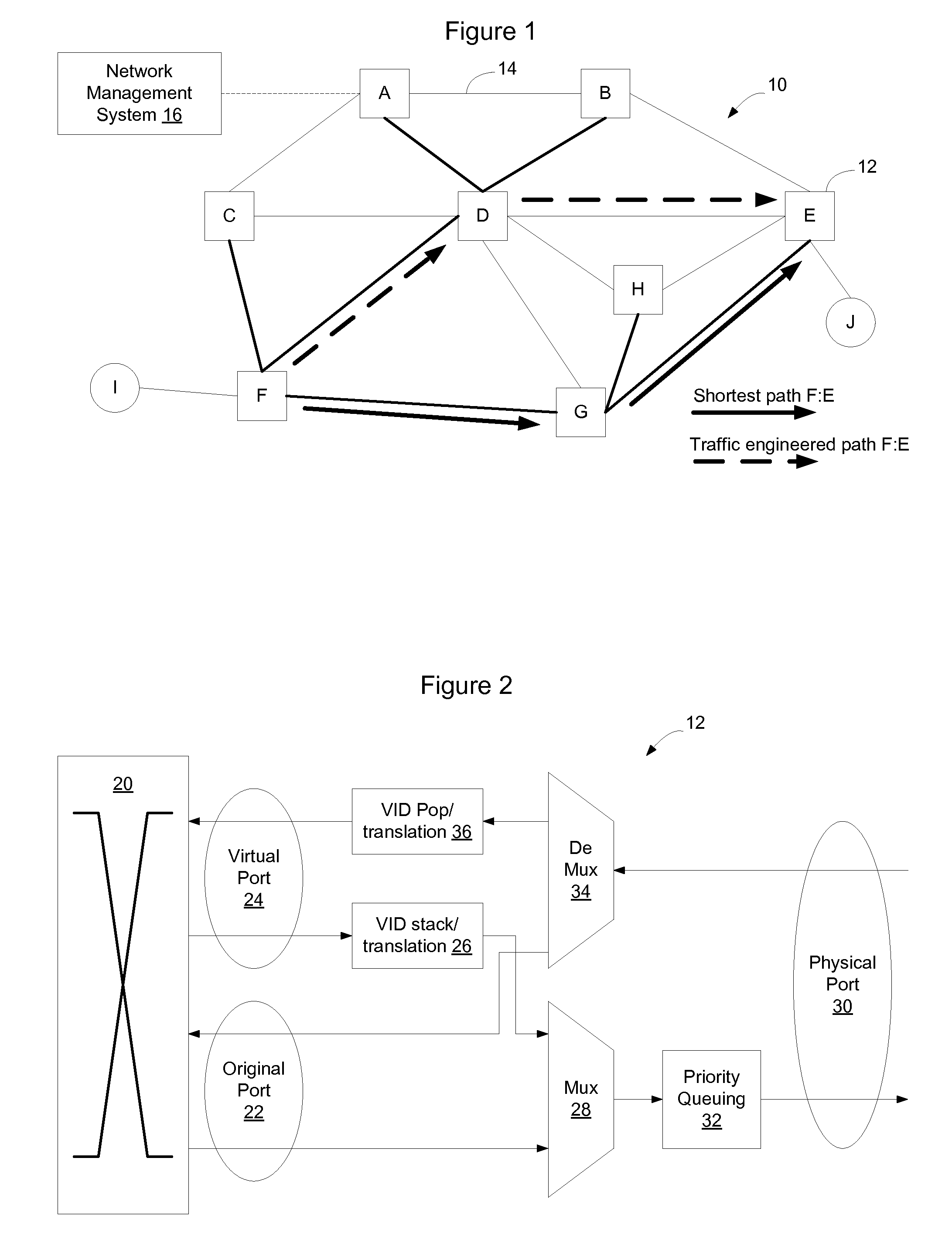
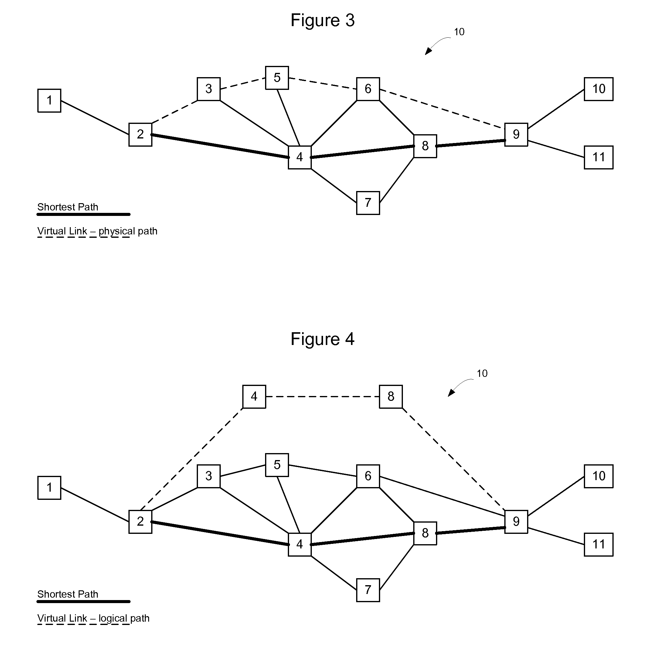
[0018]FIG. 1 shows an example Ethernet network 10 including a plurality of switches 12 interconnected by links 14. The Ethernet network will run a Spanning Tree Protocol (STP) to determine which links on the network should be active and which should be blocked. Alternatively, the Ethernet network may implement a routing protocol such as Intermediate System to Intermediate System (IS-IS) to establish more efficient use of network capacity with loop-free shortest path forwarding. An Ethernet network that implements a routing protocol such as IS-IS will be referred to herein as a Link State Protocol Controlled Ethernet Network.

[0019]In a link state protocol controlled Ethernet network, rather than utilizing a learned network view at each node by using the Spanning Tree Protocol (STP) algorithm combined with transparent bridging, the bridges forming the mesh network exchange link state advertisements to enable each node to have a synchronized view of the network topology. This is achiev...


PUM


Abstract

Virtual links may be used to divert traffic within an Ethernet network without affecting overall traffic patterns on the Ethernet network. In one embodiment, the virtual link may be established on the network via a routing system in use on the network. Nodes on a defined path for the virtual link will install forwarding state for the virtual link so that traffic may follow the defined path through the network. The logical view of the virtual link, from a routing perspective however, has the same cost as the shortest path between the endpoints of the virtual link and, accordingly, does not affect other traffic patterns on the network. Once established, the end nodes on the virtual path will have two equal cost paths through the network—one following the shortest path tree and one along the path for the virtual link. The end nodes may use a tie breaking process in an Equal Cost Multi Path (ECMP) selection process to preferentially select the virtual link over the shortest path.

Description

TECHNICAL FIELD[0001]The present invention relates to Ethernet traffic routing protocols, and in particular to a method and apparatus for implementing virtual links in a routed Ethernet mesh network.BACKGROUND[0002]In Ethernet network architectures, devices connected to the network compete for the ability to use shared telecommunications paths at any given time. Where multiple bridges or nodes are used to interconnect network segments, multiple potential paths to the same destination often exist. The benefit of this architecture is that it provides path redundancy between bridges and permits capacity to be added to the network in the form of additional links. However to prevent loops from being formed, a spanning tree was generally used to restrict the manner in which traffic was broadcast on the network. Since routes were learned by broadcasting a frame and waiting for a response, and since both the request and response would follow the spanning tree, all of the traffic would follo...

Claims


Application Information

Patent Timeline
Patent Type & Authority Applications(United States)
IPC IPC(8): H04L12/56H04L45/02H04L45/24
CPCH04L45/02H04L45/66H04L45/24H04L45/03
Inventor ALLAN, DAVIDBRAGG, NIGEL
Owner CIENA
Why Eureka
Try Eureka