
User interface for querying dependency relations between textual data elements in a memory

a textual data element and user interface technology, applied in the field of computer arrangement user interface, can solve the problems of not being able to provide all useful feedback from the index, not being able to provide a more fine-grained way of searching, not being able to give an incomplete sentence, etc., and achieve the effect of convenient and quick respons

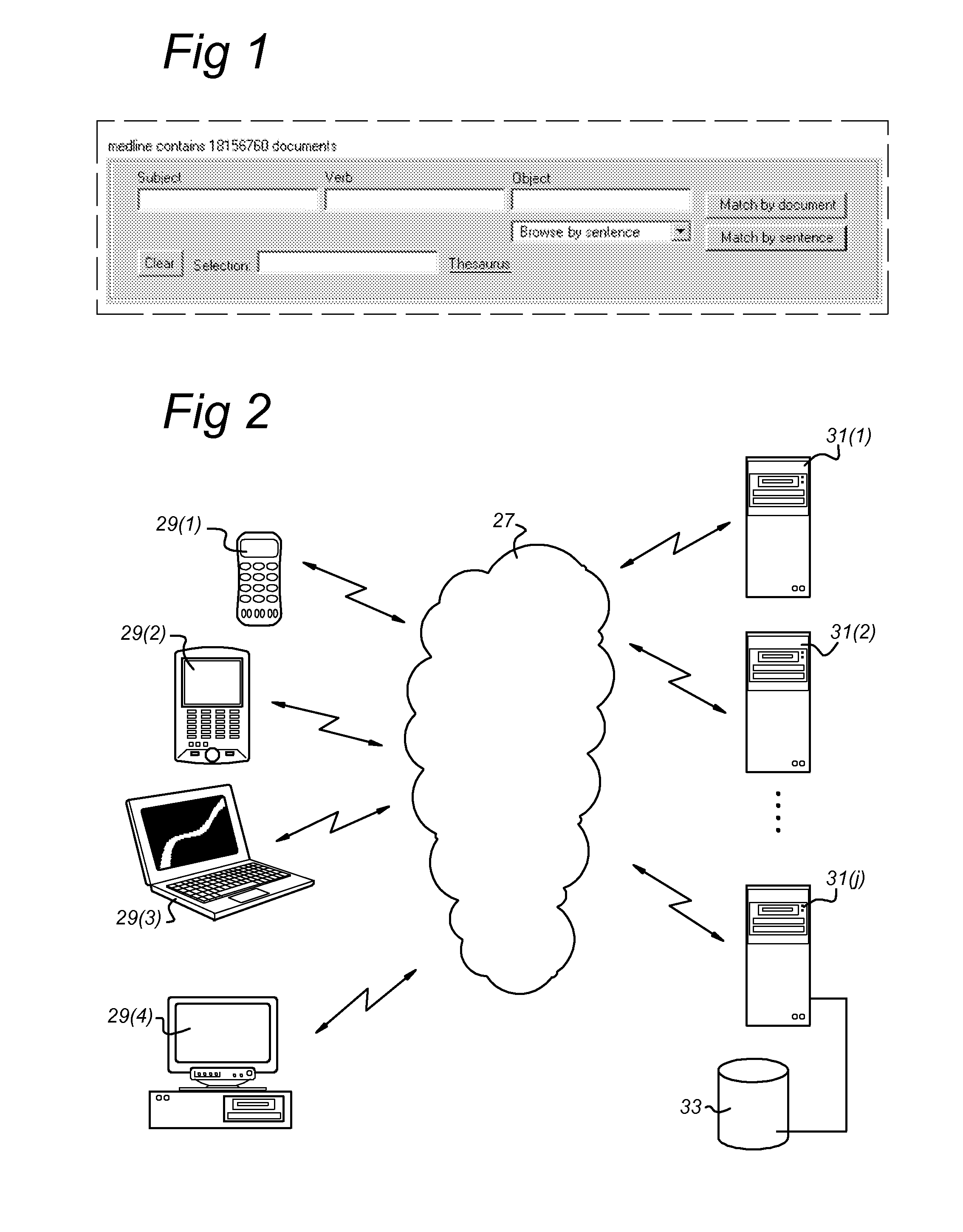
Inactive Publication Date: 2010-10-28
PHASAR
View PDF6 Cites 5 Cited by
  • Summary
  • Abstract
  • Description
  • Claims
  • Application Information

AI Technical Summary

Benefits of technology

[0055]The present invention is directed to providing a user interface allowing a user to define a dependency graph for a computer arrangement in an easier and quicker way than the prior art.
[0056]In an embodiment, the present invention is directed to an improved user interface for a computer arrangement that allows a user to easily instruct the computer arrangement to explore the dependency relations between textual items in a large collection of syntactically analysed natural language text, to construct dependency graphs from those textual items and to retrieve those graphs from the analysed collection that contain the constructed dependency graphs as a subgraph. One advantageous application is where the graphs define one or more phrases comprising items and relations between different items that are used for searching in a database.

Problems solved by technology

One of the hardest things in designing the interface is to elicit from the searcher a dependency graph without demanding undue linguistic knowledge or conveying a sense of doing linguistic work.
Letting the searcher give the query in the form of a sentence is attractive but dangerous, because sentences are often ambiguous; furthermore, it is not easy to give an incomplete sentence (leaving one or more gaps).
On the other hand, this approach is only appropriate for finding elementary sentences known as “factoids”, and does not provide a more fine-grained way of searching.
It presents the documents as a rigid database of factoids, rather than as a searchable universe, and is not capable of providing all useful feedback from the index.
This last form of matching is the most precise form of matching, but also computationally the most expensive.

Method used


Image

  • User interface for querying dependency relations between textual data elements in a memory
  • User interface for querying dependency relations between textual data elements in a memory
  • User interface for querying dependency relations between textual data elements in a memory

Examples


first embodiment

[0111]In a first embodiment, such an action is implemented by the program to allow the user to drag the cursor with mouse 15 from a position inside the box to another position over one of its sides, for instance by keeping the left mouse button pressed while moving the cursor across that side. This process is called pulling (on) that side of the box.

[0112]An action on a different side of the box may mean a different instruction to the processor 1. For instance, as shown in FIG. 5, the box has four different sides and performing an action on the sides may be converted by the computer arrangement in the following instructions:[0113]acting on the right side=instruction to add a box that functions as a modifier to the present box, meaning that the added box will be automatically connected to the box already present on the display by an arrow, where the arrow is directed from the already present box to the new box,[0114]acting on left side=instruction to add a box that functions as a hea...

second embodiment

[0119]In a second embodiment the display is a touch screen monitor that receives instructions from a user via a finger touching and or moving over the display 3. Then, the user may activate a box by touching the box on the display 3 and may perform the action as mentioned above by shifting a finger from the inside of the box to the outside over the side concerned. Alternatively, the user may perform the action on the side concerned by simply pushing with a finger one or more times on a tab shown on the touch screen, or on the location of the touch screen where the side is shown. Instead of a finger, the user may be allowed to use any other suitable means to operate the touch screen, including but not limited to any pin or stylus shaped device.

[0120]This enables, for instance, keyboardless mobile search applications that can be carried out by pda's and mobile phones.

[0121]The touch screen may be arranged to show a virtual keyboard with keys that can be touched by a user, for instance...

third embodiment

[0122]In a third embodiment, as shown in FIG. 6A, the box may have tabs along its sides, and the actions as defined above may be implemented as clicking on a tab at a specific side of the box, which may be appropriately marked:[0123]clicking on the right side tab=instruction to add a box that functions as a modifier to the present box, meaning that the added box will be automatically connected to the box already present on the display by an arrow, where the arrow is directed from the already present box to the new box,[0124]clicking on the left side tab=instruction to add a box that functions as a head to the present box, meaning that the added box will be automatically connected to the box already present on the display by an arrow, where the arrow is directed from the new box to the already present box,[0125]clicking on the lower side tab=request for feedback, when performing this action a list of possible heads or modifiers and relations will show up from which the user can make ...


PUM


Abstract

A method of and a computer arrangement for presenting a user interface on a display. A first box is presented on the display to a user, the first box having multiple sides. The user is allowed to perform an action on at least one of the sides of the box. The action is interpreted as an instruction to be carried out by the computer arrangement and the instruction is selected from a set of instructions including an instruction to establish a relation between a first term to be put into the first box by the user and a second term in a second box on the display.

Description

1. FIELD OF THE INVENTION[0001]The present invention relates to a user interface of a computer arrangement that allows a user to set up and query relations between data elements in a memory.2. BACKGROUND OF THE INVENTION[0002]PHASAR (Phrase-based Accurate Search And Retrieval) is a new kind of search engine, in which both documents and queries are represented as a collection of dependency graphs, rather than as a bag of keywords.[0003]Because both the way of matching of PHASAR and the intended way of working of the searcher are very different from those in the traditional keyword-based search engines, PHASAR has a novel Graphical User Interface (GUI), differing from traditional interfaces in functionality and behaviour. This interface (called the Dungeons-and-Dragons interface, D&D for short) was designed to make it easy for the non-linguistical user to construct a query in the form of a dependency graph interactively and in an informed way.[0004]The functions of the GUI are:[0005]t...

Claims


Application Information

Patent Timeline
IPC IPC(8): G06F3/048G06F17/30
CPCG06F17/2785G06F17/30401G06F17/30398G06F16/243G06F16/2428G06F40/30
Inventor KOSTER, CORNELIS HERMANUS ANTONIUS
Owner PHASAR
Learn More