Switchable power combiner

a power combiner and switch technology, applied in piezoelectric/electrostrictive/magnetostrictive devices, amplifiers, semiconductor devices/discharge tubes, etc., can solve the problems of power amplifiers that are less efficient at coupling power into antennas, antenna impedances vary, power amplifiers that are efficiently switched on or off, etc.

Inactive Publication Date: 2010-11-04
CYMATICS LAB CORP
View PDF13 Cites 37 Cited by
  • Summary
  • Abstract
  • Description
  • Claims
  • Application Information

AI Technical Summary

Benefits of technology

The patent describes a switchable power combiner that can efficiently switch on or off RF power amplifiers and other circuits. It uses a piezoelectric transformer that can be controlled to couple energy between its primary and secondary sections using a switchable piezoelectric material. The transformer section has multiple differential amplifiers or other circuits connected to it, which can be activated or deactivated by applying a threshold condition to the switchable piezoelectric material. The technical effect of this invention is the ability to efficiently control the reconfiguration of RF power amplifiers and other circuits using a single switch.

Problems solved by technology

The technical problem addressed in this patent text is the need for a power combiner that can efficiently match the impedance of the antenna in a wireless communication device, such as a mobile phone, and deliver power to the antenna with high efficiency in both back-off and operation. Previous solutions, such as PIN diodes and GaAs FET switches, have resulted in high power consumption and loss of efficiency. The patent seeks to address this problem by providing a new power combiner design that can adapt to changes in antenna impedance and efficiently match the optimal load impedance of the power amplifier to the antenna.

Method used


Image

  • Switchable power combiner
  • Switchable power combiner
  • Switchable power combiner

Examples


second embodiment

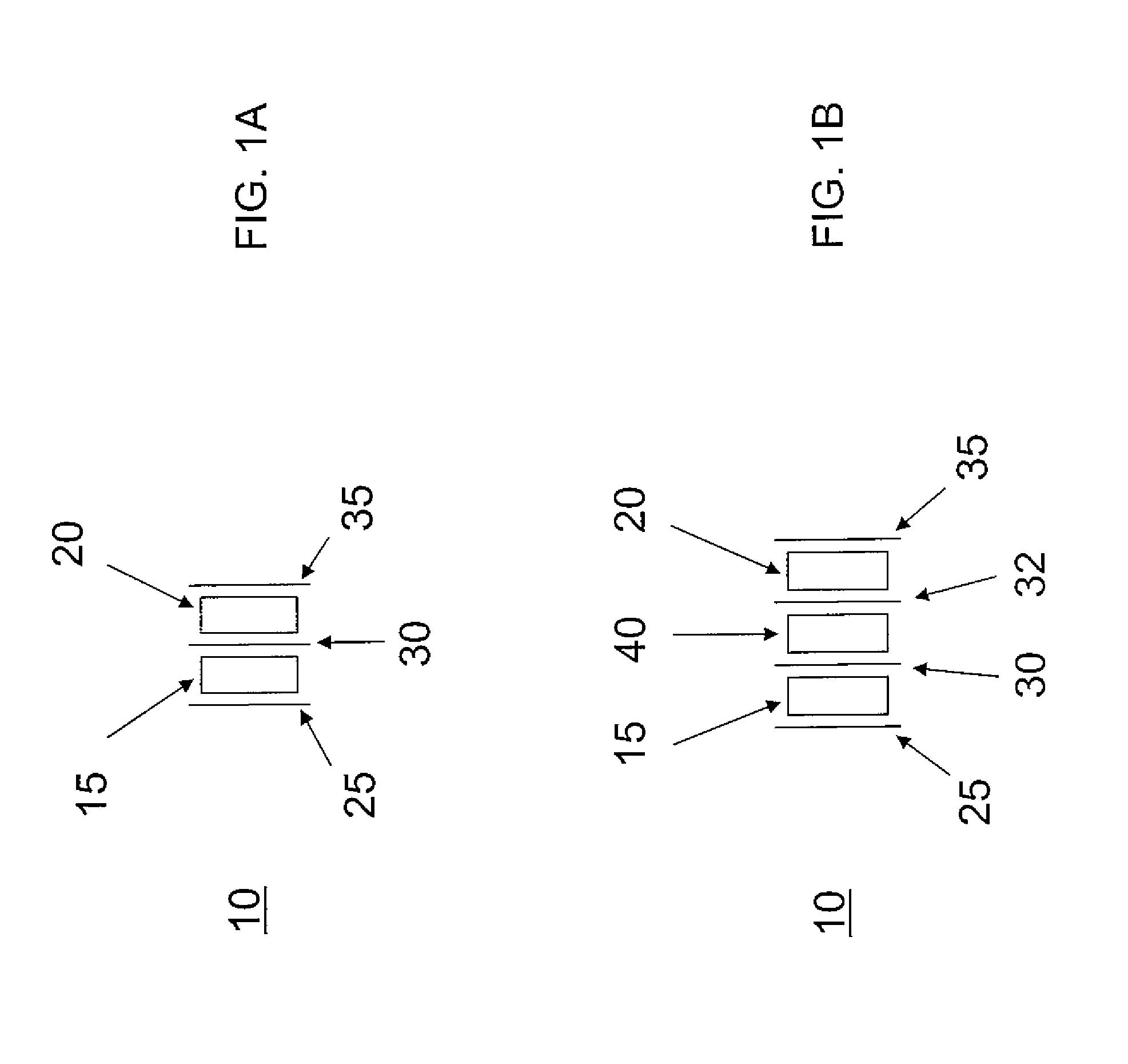
[0027]the switchable transformer is illustrated in FIG. 1B. In this embodiment, the transformer 10 has acoustic coupling layers 40 inserted between the primary 15 and the secondary 20. In this structure, the primary and secondary do not share a common electrode, and the electrodes for the primary and secondary are electrically separated by the coupling layers 40, which include at least one layer of dielectric material. Such a switchable transformer is useful where more that one switchable transformer is in use and in applications that requires the ability to independently and separately connect to the electrodes in the transformer. In addition, the coupling layers 40 can serve to broaden the bandwidth of the transformer, as one skilled in the art will appreciate.

[0028]The primary 15 and secondary 20 of the transformer are made of piezoelectric or switchable piezoelectric materials. At least one of the primary 15 and the secondary 20 is made of a switchable piezoelectric material.

[00...

third embodiment

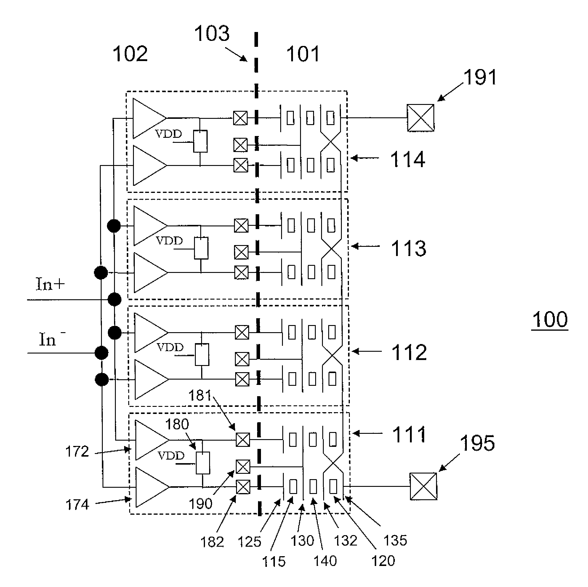
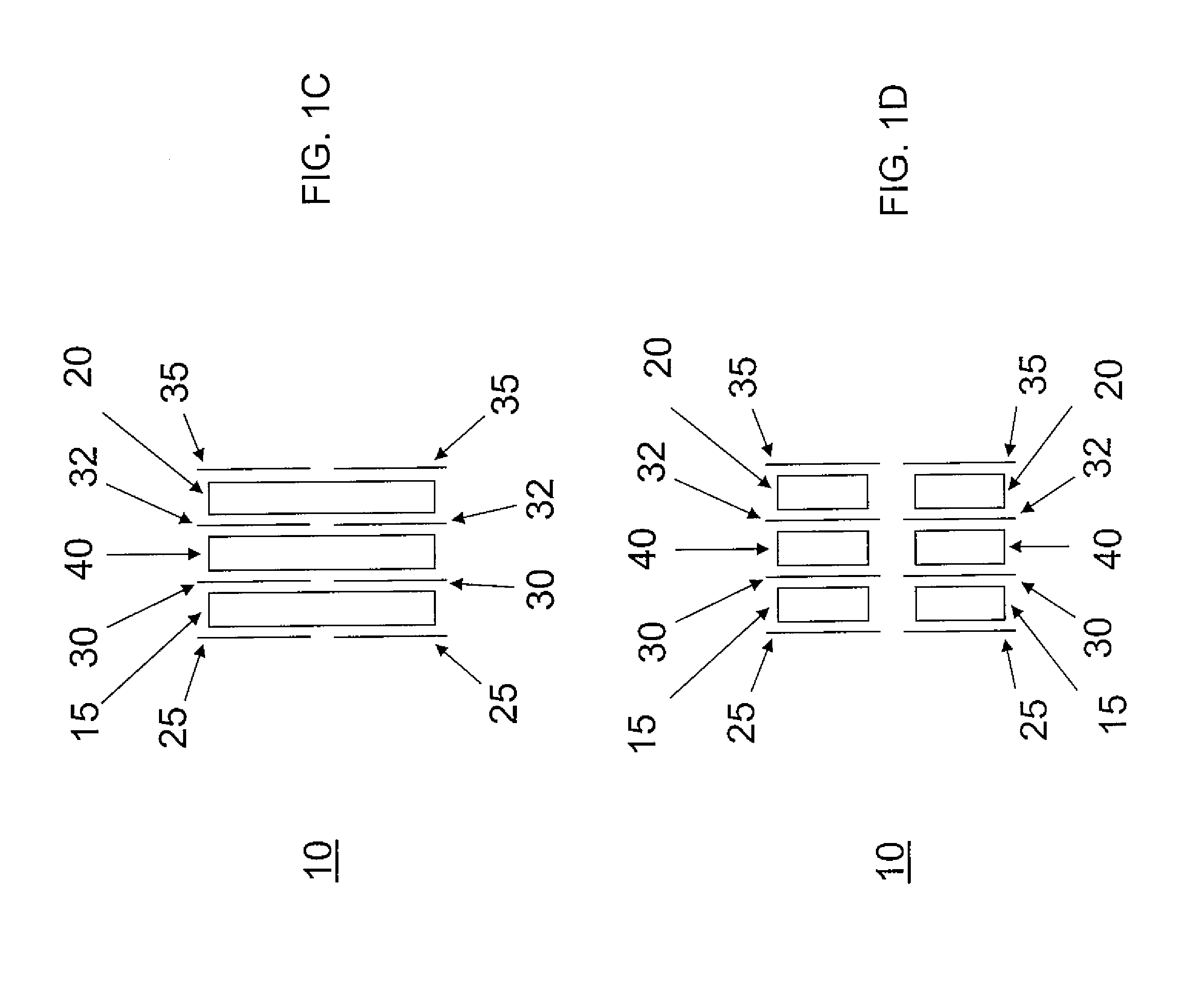
[0031]the switchable transformer is illustrated in FIG. 1C. This switchable transformer has electrodes 25, 30, 32 and 35 that are segmented, and it is otherwise similar to that illustrated in FIG. 1B. The switchable transformer with segmented electrodes can be configured for multiple purposes by electrically connecting the segmented electrodes. For example, as illustrated below, a switchable power combiner can be implemented by connecting a segmented switchable transformer (with the primary made of a switchable piezoelectric material) to have multiple separate primaries and a common secondary, such that any or all primaries may be acoustically coupled to the common secondary. As a second example, also illustrated below, a differential to single-ended converter can be implemented by connecting a two-segment segmented transformer with the primary or secondary electrodes crossed-over between the two segments.

fourth embodiment

[0032]the switchable transformer is illustrated in FIG. 1D. In this embodiment, the transformer 10 has segmented electrodes 25, 30, 32 and 35, as well as a segmented primary 15, segmented coupling layers 40, and a segmented secondary 20. This transformer is functionally equivalent to the embodiment illustrated in FIG. 1C, but the segmentation of the acoustically active layers facilitates manufacturing and it facilitates the suppression of undesired acoustic coupling between segments (e.g., between segmented primaries) of a segmented transformer.


PUM


Abstract

A switchable power combiner is disclosed. The switchable power combiner has an output section that is a signal source connected to a transformer section. The transformer section has one or more primaries and a common secondary. The transformer primaries and secondary are acoustically coupled. The primaries or/and the secondary are made of switchable piezoelectric material, such that the acoustic coupling between any primary and the secondary can be switched on or off by electrical control, thereby implementing a switchable power combiner. The transformer secondary is connected to an antenna port. The power amplifier output section is segmented and connected to the transformer primaries. The power amplifier output section has a plurality of power amplifiers and a plurality of reactance elements, either fixed or variable. The switchable power combiner generates different linear load lines by switching on and off the coupling between any primary and the secondary.

Description


Claims


Application Information

Patent Timeline
Owner CYMATICS LAB CORP
Why Eureka
Try Eureka