Earpiece

a technology of earpieces and ear plugs, applied in the field of earpieces, can solve the problems of not being able to meet the needs of mobile devices, not being able to meet the needs of mass production, and ear plugs blocking the ear canal, so as to achieve the effect of improving comfor

Active Publication Date: 2010-11-04
FREEBIT AS
View PDF33 Cites 90 Cited by
  • Summary
  • Abstract
  • Description
  • Claims
  • Application Information

AI Technical Summary

Benefits of technology

[0012]The shape of the ear unit keeps the ear canal to certain degree open towards the outer environment for improved comfort when compared to a unit that closes or blocks the ear canal.

Problems solved by technology

Such devices are not well suited for use with mobile apparatuses since the device should have a form that makes it easy to stow it in a pocket, bag or the like when not in use.
These are not suited for mass production since each has to be adapted to each user for the stable positioning and comfortable use.
Also an ear plug will block the ear canal and appear uncomfortable to a user.
Moreover the natural production of ear wax will not escape, thus necessitating flushing of the ear at regular intervals.
Ear pieces for walkmen and the like are known, using the outer part of the ear for attachment, yet these have a circular shape and exploit only the lower part of the outer cavity of an ear for attachment and small differences in the size of the ear will cause said ear pieces not to fit particularly well.
The disadvantage is the constant outward pressure being exerted which over time can lead to discomfort.

Method used


Image

  • Earpiece
  • Earpiece
  • Earpiece

Examples


Embodiment Construction

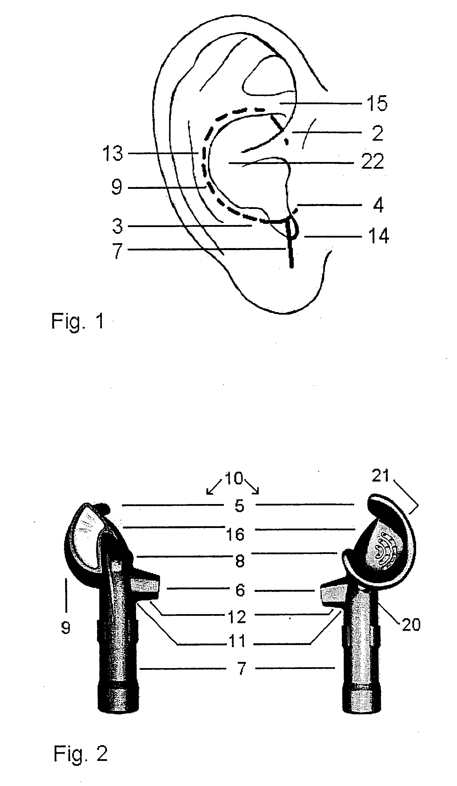
[0019]FIG. 1 shows schematically an ear with a decremental curve 1 inserted. As shown by the figure the outer periphery of the ear unit is held in the ear by the outer parts of the ear such that the lower part of the antihelix 13, antitragus 3 and tragus 4 of the ear and part extending downwards 7, but intertragic notch 14. Parts of the curve is positioned inside the antihelix 13 when viewed from the outside of the ear where said parts therefore are not visible.

[0020]By the present invention, a larger part of the outer ear is utilized, thus achieving high stability while providing more comfort to the user than the previously known solutions. The present invention also utilizes the upper part of the antihelix 13 and the cavity covered by the lower node 15 of the antihelix and the flap 2 covering said cavity by the outer part of the ear adjacent to the head.

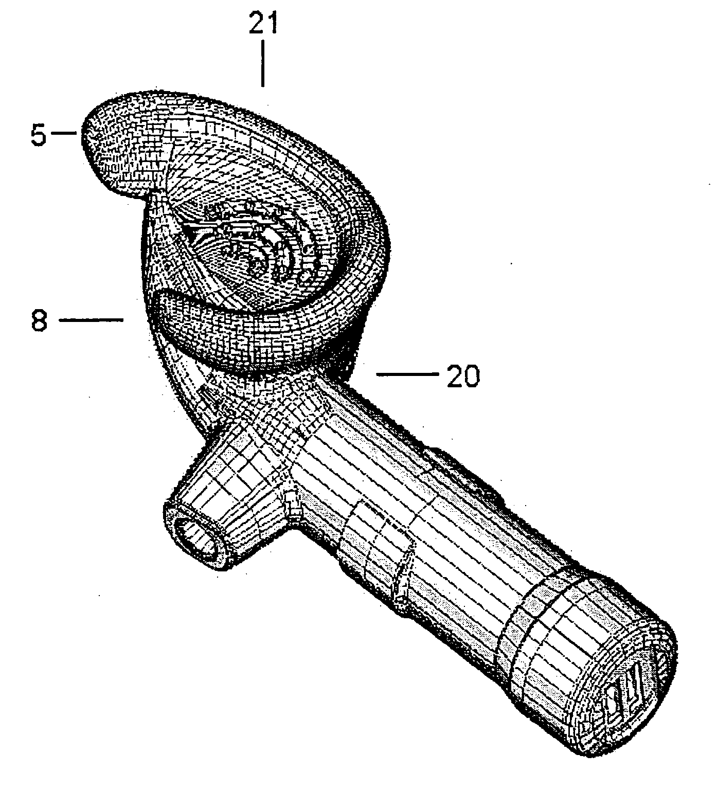
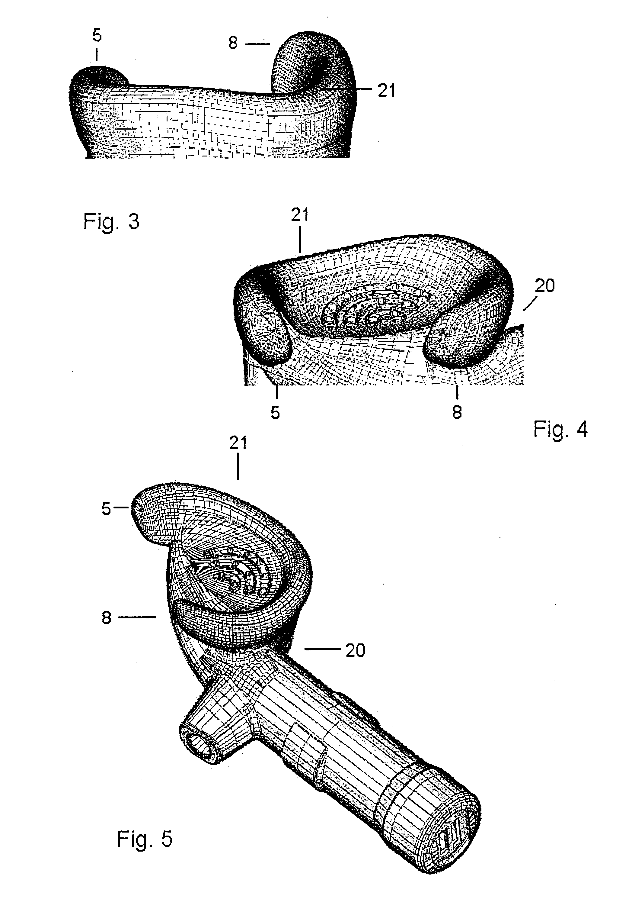
[0021]The ear unit 10 according to the present invention is shown schematically in FIG. 2, with a microphone 6 and optionally a m...


PUM


Abstract

Device called ear unit for stable fittings in an ear, characterised in that said ear unit (10) is shaped as a decremental curve and that the distance between the ends (5, 8) of the decremental curve is approximately equal to the distance between a first cavity from the under the tragus (4) of the ear and second cavity covered by the lower node (15) of the antihelix of the ear, the upper part of the curve projecting in underneath a flap (2) covering the lower part of the second cavity, and said ear piece having a curvature providing an improved attachment in that said curvature follows the bottom of the ear mussel (22). The ear unit (10) optionally comprises a part (T) extending downwards, the transition between said part (T) and the ear piece is formed in such a way that it aligns along the intertragic notch (14). The ear unit is optionally arranged with at least one unit from the group comprising ear phone and microphone. The ear unit is optionally arranged with a unit from the group of wireless communication unit for use with mobile phone and the like, and wired communication unit for use with music system and the like. Said ear unit (10) is arranged with a curvature (21) in such a way that it traces along the bottom of the ear mussel (22) when the ear unit (10) is positioned into the ear and optionally arranged with an incision (20) in such a way that it aligns along the intertragic notch (14) when said ear unit is brought into the ear. This provides a further stability and increased comfort.

Description

BACKGROUND OF THE INVENTION[0001]1. Filed of the Invention[0002]The present invention regards a device for removable attachment to the ear as disclosed in the preamble of claim 1.[0003]2. Background Information[0004]Microphone / earpiece combinations, wireless or attached by wire, to telephones, music systems, switchboards etc. are well known. Such known devices, however, frequently use a bow for the earpieces and a microphone attached to said bow. Such devices are not well suited for use with mobile apparatuses since the device should have a form that makes it easy to stow it in a pocket, bag or the like when not in use.[0005]From the prior art one should refer to U.S. Pat. No. 6,122,388 and U.S. Pat. No. 5,659,156. These are earmold devices where a plug is brought into the ear canal and are typically used in hearing devices. These are not suited for mass production since each has to be adapted to each user for the stable positioning and comfortable use. This is particularly due to t...

Claims


Application Information

Patent Timeline
Patent Type & Authority Applications(United States)
IPC IPC(8): H04R5/02H04R1/10
CPCH04R1/1016H04R1/105H04R5/033H04R1/1091H04R2201/107H04R1/10H04M1/05H04R2225/025
Inventor BERG, RICHARD STEENFELDT
Owner FREEBIT AS
Why Eureka
Try Eureka