Storage card socket for bidirectional electrical connection
- Summary
- Abstract
- Description
- Claims
- Application Information
AI Technical Summary
Benefits of technology
Problems solved by technology
Method used
Image

Examples
first embodiment
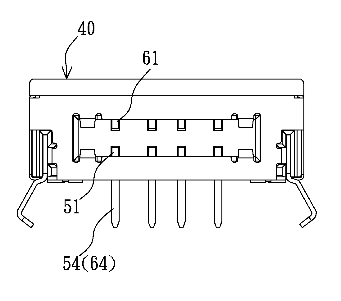
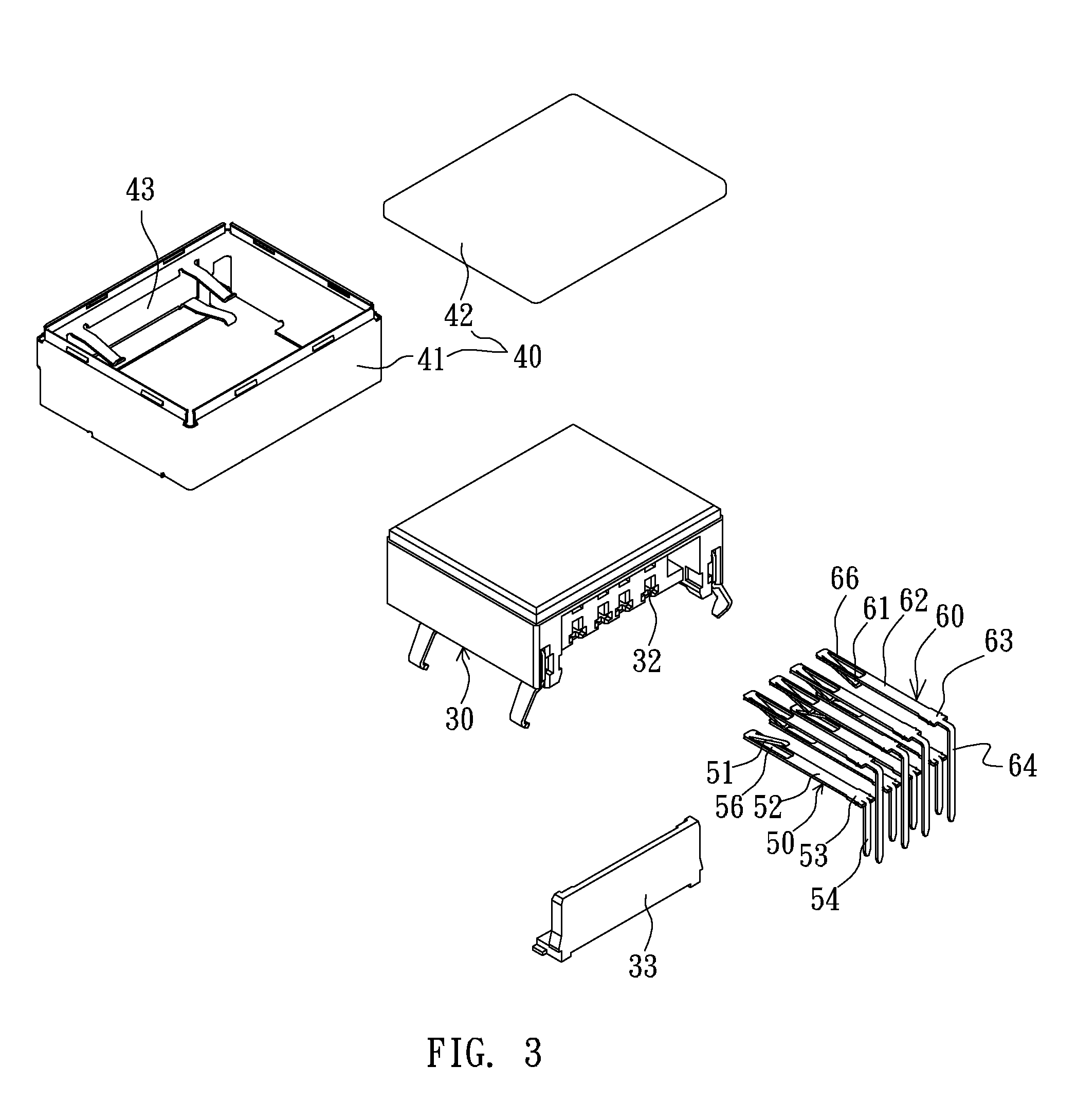
[0049]Referring to FIGS. 3 to 5, the invention is directed to a USB 2.0 storage card socket including a plastic base 30, a metal casing 40, one row of first lower terminals 50 and one row of first upper terminals 60.
[0050]The plastic base 30 is integrally formed with a connection slot 31, and the rear end of the plastic base 30 has two rows of terminal slots 32. In addition, a rear cover 33 is provided to cover the plastic base 30 from bottom to top. The connection slot 31 is disposed in the front section of the plastic base 30, and the plastic base 30 has an inserting port 34 and opposite top and bottom surfaces 35 and 36. The connection slot 31 may be connected to a plug of a storage card.
[0051]The metal casing 40 covers the plastic base 30 and has a main body 41 and an upper cover 42 covering the main body 41. The main body has front, rear, left and right surfaces. The front surface of the main body is formed with an opening 43 corresponding to the inserting port 34 of the connec...
fifth embodiment
[0067]As shown in FIGS. 19 to 21, the invention is a USB 3.0 storage card socket including a plastic base 30, a metal casing 40, one row of first lower terminals 50, one row of first upper terminals 60, a lower circuit board 100, an upper circuit board 110 and one row of pin portions 120.
[0068]The plastic base 30 is integrally formed with a connection slot 31, and a rear cover 33 is provided to cover the rear end of the plastic base 30 from bottom to top. The connection slot 31 is disposed on the front section of the plastic base 30 and may be connected to a plug of a storage card.
[0069]The metal casing 40 covers the plastic base 30 and has a main body 41 and an upper cover 42 covering the main body 41. The main body has front, rear, left and right surfaces and the front surface of the main body is formed with an opening corresponding to the inserting port of the connection slot 31.
[0070]The one row of first lower terminals 50 include four terminals. The first lower terminal 50 is i...
sixth embodiment
[0076]As shown in FIGS. 22 to 25, the invention includes a plastic base 30, a metal casing 40, one row of first lower terminals 50 and one row of first upper terminals 60.
[0077]The plastic base 30 is integrally formed with a connection slot 31. The rear end of the plastic base 30 is formed with two rows of terminal slots 32, and a rear cover 33 is provided to cover the rear end of the plastic base 30 from bottom to top. The connection slot 31 is disposed on the front section of the plastic base 30 and has an inserting port 34 and opposite top and bottom surfaces 35 and 36. The connection slot 31 may be connected to a plug of a storage card. Two rows of separately arranged terminal slots 39 are respectively disposed above and below the connection slot 31.
[0078]The metal casing 40 covers the plastic base 30 and has a main body 41 and an upper cover 42 covering the main body 41. The main body 41 has front, rear, left and right surfaces, and the front surface of the main body 41 is form...
PUM
 Abstract
Description
Claims
Application Information
 - Generate Ideas
- Intellectual Property
- Life Sciences
- Materials
- Tech Scout
- Unparalleled Data Quality
- Higher Quality Content
- 60% Fewer Hallucinations
Browse by: Latest US Patents, China's latest patents, Technical Efficacy Thesaurus, Application Domain, Technology Topic, Popular Technical Reports.
© 2025 PatSnap. All rights reserved.Legal|Privacy policy|Modern Slavery Act Transparency Statement|Sitemap|About US| Contact US: help@patsnap.com