Bearing puller

a technology of bearings and pullers, applied in the field of bearings, can solve the problems of affecting the quality of the bearings, and affecting the performance of the bearings, etc., and achieves the effects of convenient and precise fitting, safe and efficient manner and tooling, and high efficiency

Active Publication Date: 2010-11-11
PUNARO MICHAEL J
View PDF7 Cites 8 Cited by
  • Summary
  • Abstract
  • Description
  • Claims
  • Application Information

AI Technical Summary

Benefits of technology

[0006]In accordance with the present invention, there is provided . . . a novel and improved puller that provides a safe and efficient manner and tooling to remove bearings, bushings, gears, etc. The invention is simple and highly efficient is its design and use due to incorporating multiple design elements into the main collets or bearing adapters. My present invention uses a simple split collet machined accurately to precisely fit the bearing being removed, in addition the same collet incorporates an upper threaded section to allow the removal sleeve to easily and precisely fit to the collet while at the same time the threaded removal sleeve securely keeps the collet together and properly aligned with the bearing and shaft axis to provide easy and accurate operation. Once assembled you have a robust and centrally aligned tool which easily removes the bearing or bushing. Another design integrated into my puller is the ball thrust bearing on the end of the pressure or removal screw. This anti-friction thrust bearing eliminates undue friction and provides very free rotation of the pressure screw.
[0007]It would be advantageous to provide a . . . one piece designed and machined collet that is then split and kept in a matched set so that you have a very accurate and precise tool that precisely fits the bearing to assure the assembled puller is in precise alignment to the axis of the shaft.
[0008]It would also be advantageous to provide a . . . secure and safe assembled puller assembly that can not slip off of the bearing or introduce any misalignment during the removal operation.
[0009]It would further be advantageous to provide a . . . secure and close fitting puller assembly that will allow access to bearings that are very difficult to remove with conventional jaw type pullers.

Problems solved by technology

Although we have been using these anti-friction bearings and bushings for many years the maintenance and normal wear and tear present certain problems due to the size and space restrictions placed on them by engineering standards and design limitations from different manufactures on the mechanical devices and machinery they design that use bearings and bushings.
Due to the design of these pullers the assembled puller may be out of alignment with the central axis of the bearing, bushing, or gear etc that is being removed due to the fact that the t-bar design may easily be installed inefficiently if the bolts threaded into the bearing separator or collet are not drawn down evenly and the t-bar or flange will be at an angle to the central axis of the bearing mount or bore.
This will introduce excessive friction and resistance to the bearing being removed and may damage the component the bearing is being removed from.
Another problem with theses designs is that they take much room to be assembled to the bearings or bushings etc and sometimes there is very limited room to work.
The referenced jaw type, bar type, and split sleeve pullers all have a pressure screw that creates friction may also create undue wear on the component it is applied against since there is no provision for a thrust bearing.
The adapter then is fit into the end of the pressure screw and may allow the pressure screw to rotate while the adapter is stationary but this method creates undue friction and stress since there are no anti-friction bearings involved.
Another problem with the jaw and bar type pullers is that they require a large clearance area around the bearing and surrounding assembly.

Method used


Image

  • Bearing puller
  • Bearing puller
  • Bearing puller

Examples


Embodiment Construction

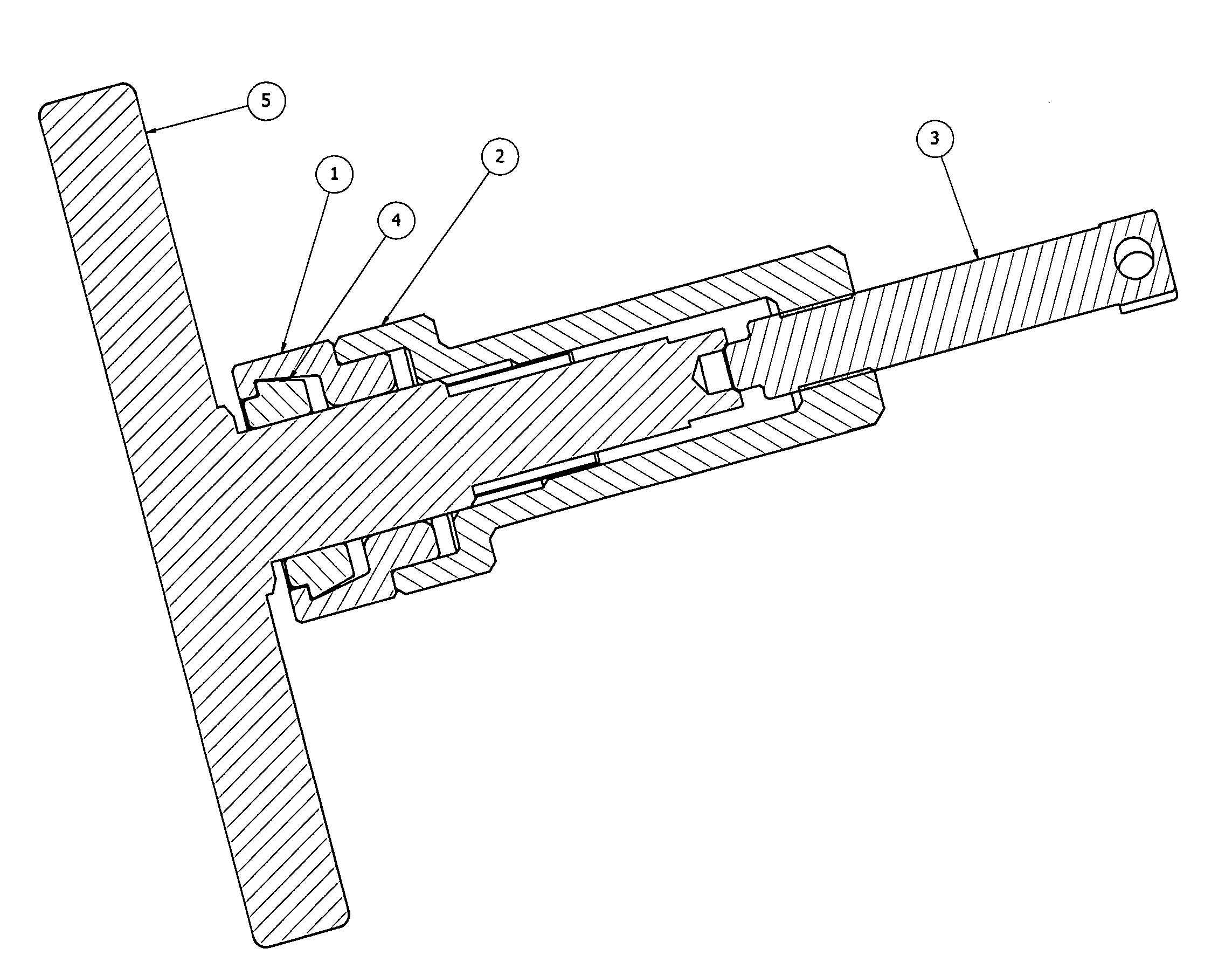
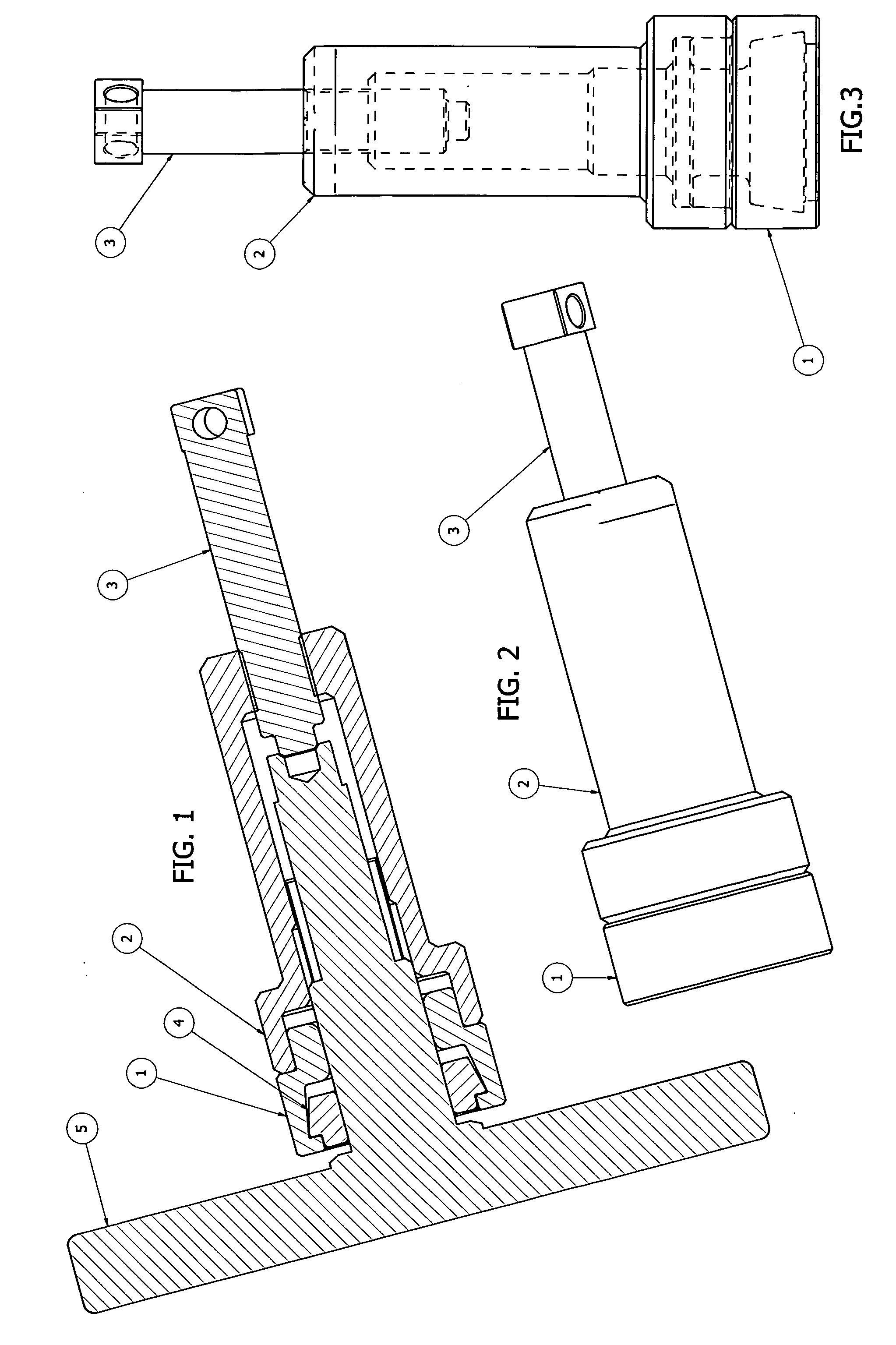
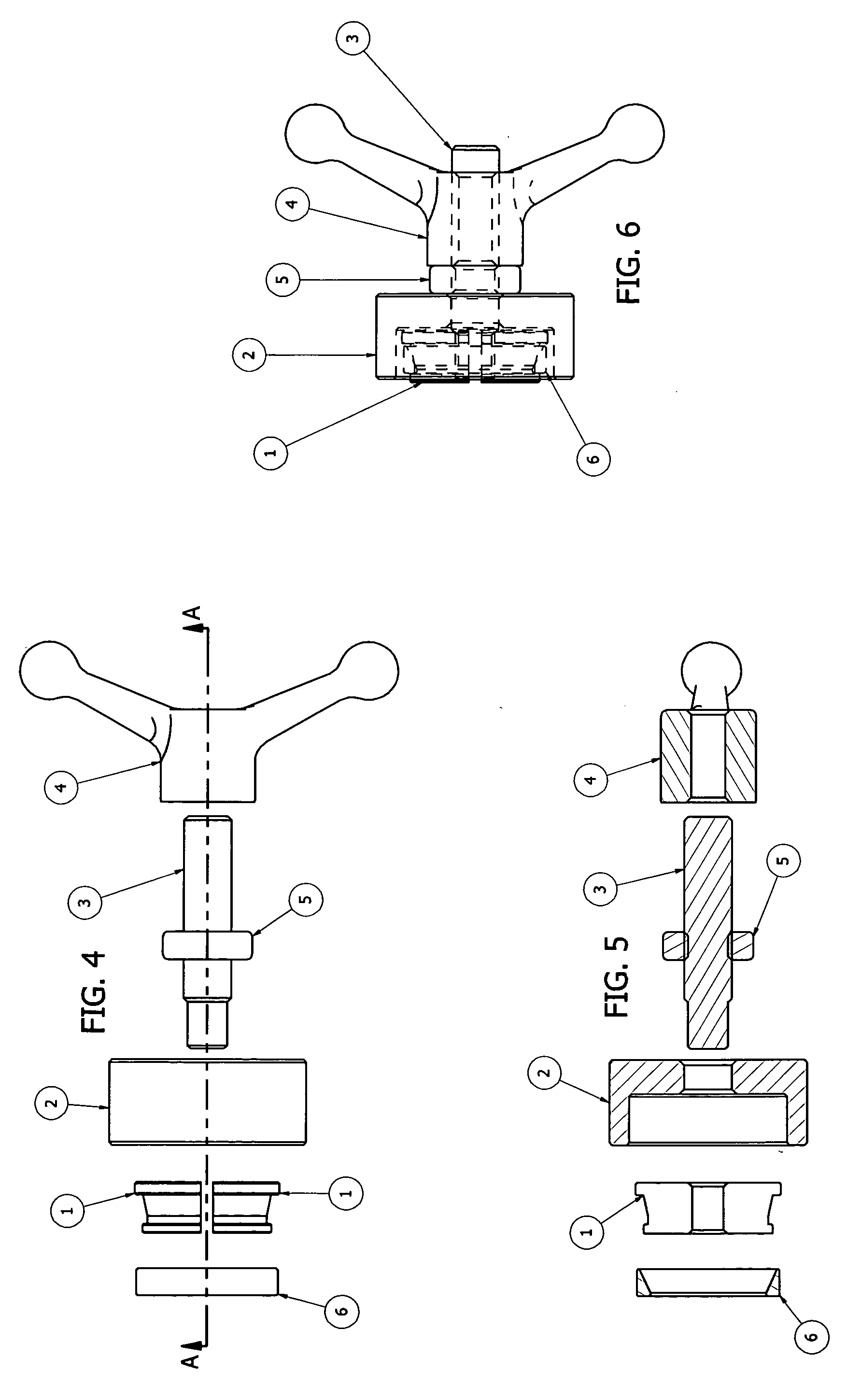
[0024]Referring to FIG. 4, I have a split collet 12 that by design accomplishes several tasks at once. The inside bore of the collet 121 is threaded to accept the removal screw 3 (pressure screw 16) that expands the collet 12 to the inside bore of the bearing 6 or bushing for a secure slip free fit. Since the split collet 121 is threaded the removal screw 3 will bottom out on the top flange of the collet 121 thereby aligning the upper flange halves on the same plane. The collet 121 and screw 3 now are secure and centrally affixed to the bearing axis. The common problem of present day split collet 12 designs id eliminated. This problem is as follows, a tapered expander rod and tapered ID or ball and ramp design allows a pivot point that lets the collet 12 flange pivot inward and slip right out of the bearing ID as pressure is applied, usually by the force of a slide hammer which introduces a shocking mechanism to further advance the problem of pulling the collet 12 right out of the b...


PUM

PropertyMeasurementUnit
rotational frictionaaaaaaaaaa
pressureaaaaaaaaaa
sizeaaaaaaaaaa

Abstract

A novel and improved puller that provides a safe and efficient manner and tooling to remove bearings, bushings, gears, etc. The invention is simple and highly efficient is its design and use due to incorporating multiple design elements into the main collets or bearing adapters. My present invention uses a simple split collet machined accurately to precisely fit the bearing being removed, in addition the same collet incorporates an upper threaded section to allow the removal sleeve to easily and precisely fit to the collet while at the same time the threaded removal sleeve securely keeps the collet together and properly aligned with the bearing and shaft axis to provide easy and accurate operation. Another design integrated into my puller is the ball thrust bearing on the end of the pressure or removal screw. This anti-friction thrust bearing eliminates undue friction and provides very free rotation of the pressure screw.

Description

RELATED APPLICATIONS[0001]The present application is a continuation application of U.S. provisional patent application Ser. No. 61 / 065,651, filed Feb. 14, 2008, for BEARING PULER, included by reference herein and for which benefit of the priority date is hereby claimed.FIELD OF THE INVENTION[0002]The present invention relates to an improved puller that will provide a safe and efficient manner and tooling to remove bearings, bushings and gears.BACKGROUND OF THE INVENTION[0003]Bearings & bushings are widely used in many mechanical applications and require routine maintenance and / or replacement to prevent failure and to keep the mechanisms operating at optimum levels of performance. Although we have been using these anti-friction bearings and bushings for many years the maintenance and normal wear and tear present certain problems due to the size and space restrictions placed on them by engineering standards and design limitations from different manufactures on the mechanical devices a...

Claims


Application Information

Patent Timeline
Patent Type & Authority Applications(United States)
IPC IPC(8): B23P19/04
CPCB25B27/062Y10T29/53857Y10T29/53909Y10T29/53943Y10T292/228
Inventor PUNARO, MICHAEL J.
Owner PUNARO MICHAEL J
Why Eureka
Try Eureka