Positive displacement flowmeter

a flowmeter and positive displacement technology, applied in the direction of volume/mass flow measurement, measurement devices, instruments, etc., can solve the problems of disassembly, function or production disadvantages of the rotor of the flowmeter, and achieve the effect of avoiding abnormal engagement, excellent abrasion resistance, and high torque efficiency

Inactive Publication Date: 2010-11-11
OVAL CORP
View PDF1 Cites 1 Cited by
  • Summary
  • Abstract
  • Description
  • Claims
  • Application Information

AI Technical Summary

Benefits of technology

[0016]According to the present invention, excellent abrasion resistance is achieved since a pair of non-circular gears of a positive displacement flowmeter makes rolling contact without slip on a pitch line; a higher torque efficiency is achieved since a larger value can be given to a tooth height ratio; and it is possible to form the gears in spur shape instead of helical shape while avoiding abnormal engagement since apparent backlash is provided.

Problems solved by technology

This is disadvantageous to a rotor of a flowmeter in aspect of function or production.

Method used


Image

  • Positive displacement flowmeter
  • Positive displacement flowmeter
  • Positive displacement flowmeter

Examples


Embodiment Construction

[0022]Preferred embodiments of a positive displacement flowmeter of the present invention will now be described with reference to the accompanying drawings.

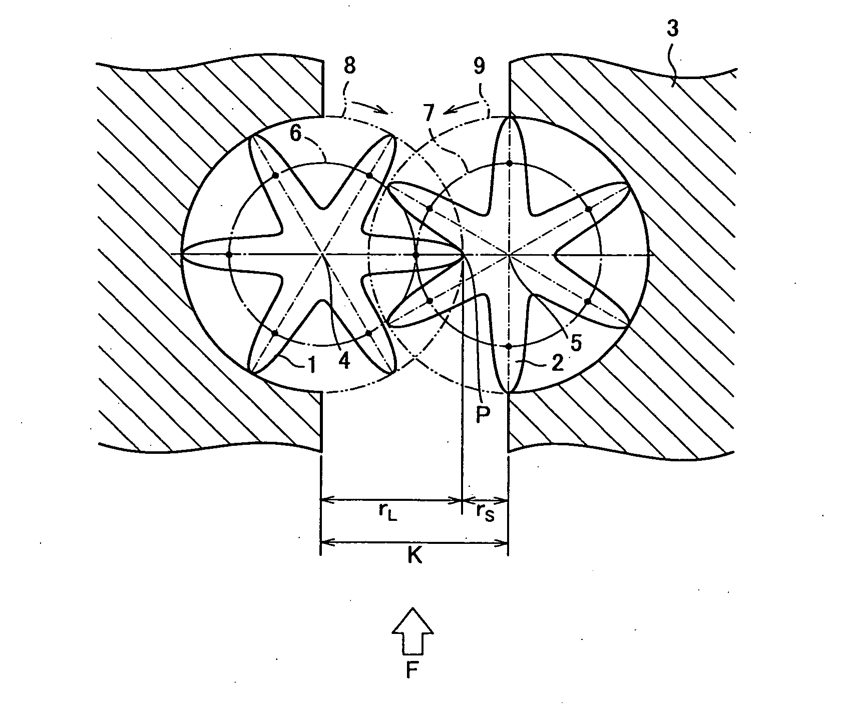
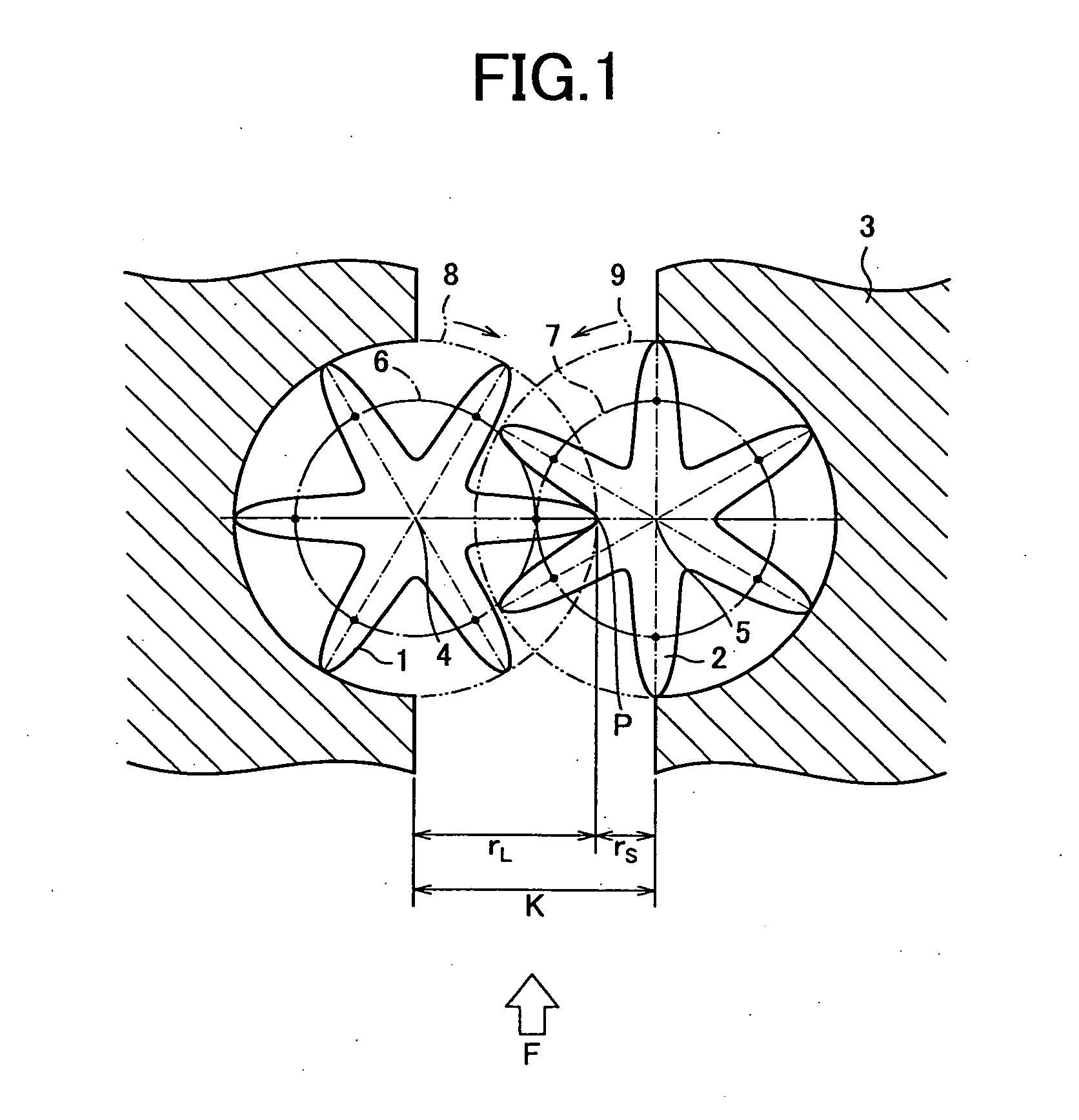
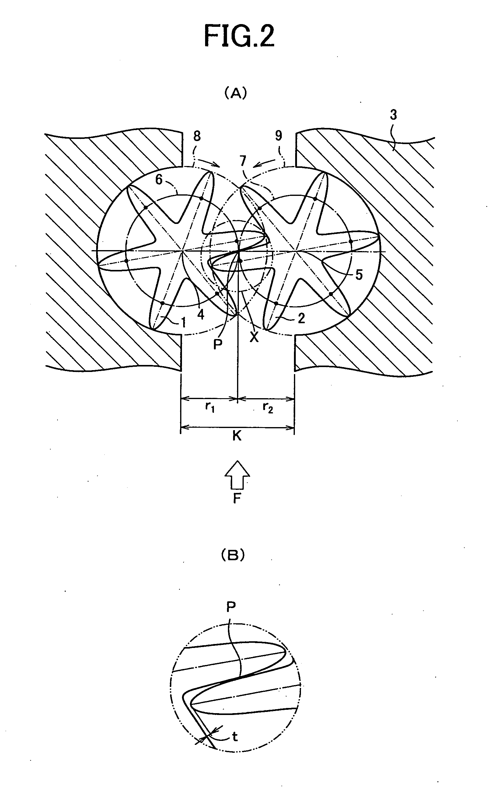
[0023]FIG. 1 is a diagram of an exemplary configuration of a positive displacement flowmeter according to one embodiment of the present invention. In FIGS. 1, 1 and 2 denote a pair of rotors; 3 denotes a casing; 4 an 5 denote axial centers of the rotors 1 and 2, respectively; 6 denotes a virtual pitch circle of the rotor 1; 7 denotes a virtual pitch circle of the rotor 2; 8 denotes an addendum circle of the rotor 1; and 9 denotes an addendum circle of the rotor 2. A pair of the rotors 1, 2 is housed in the casing 3 of the positive displacement flowmeter rotatably around the axial centers 4, 5. The rotors 1, 2 are formed in spur shape and use a tooth profile curve that is an oval pitch curve itself having a locus of a contact point P on a pitch line that links the axial centers 4 and 5 and satisfy the following rolling contact con...


PUM


Abstract

A position displacement flowmeter having a pair of non-circular gears in a rolling contact on a pitch line without slippage. The positive displacement flowmeter comprises a casing and a pair of rotors provided in the casing and rotatable around its center axes. The pair of rotors have a tooth profile curve which is an oval pitch curve itself having a trajectory of contact points on the pitch line, and they satisfy a condition of r1+r2=K=const r11=r22, and a moving radius of the oval pitch curve is given by ri=a/(1−bcosnθi) (i=1, 2), where “ri(i=1, 2)” is the moving radius that is a distance from a center of rotation to the oval pitch curve, “a” is a homothetic coefficient, “b” is a flattening, “n” is a number of lobes, and “θi(i=1, 2) is a moving angle.

Description

TECHNICAL FIELD[0001]The present invention relates to a positive displacement flowmeter and, more particularly, to a positive displacement flowmeter using a pitch curve itself of non-circular gears as a rotor tooth profile.BACKGROUND OF THE INVENTION[0002]A locus of a contact point of external gear tooth profiles making continuous contact generally forms a lemniscate loop curve and if this loop is flattened toward a center line between axes and coincides with the center line, the contact point moves on the center of both gears. Therefore, the tooth profile has a contour that achieves rolling motion, which corresponds to a pitch curve of non-uniform speed gear (non-circular gear).[0003]A contour of a rolling contact wheel which has a constant center distance and an angular velocity ratio that varies during rotation is a non-circular curve and a non-circular gear is a gear provided with teeth using this non-circular curve as a pitch curve to ensure transmission. A transmissible tooth ...

Claims


Application Information

Patent Timeline
Patent Type & Authority Applications(United States)
IPC IPC(8): G01F3/10
CPCG01F3/10
Inventor ONO, SEIGOUCHIDA, KATSUICHI
Owner OVAL CORP
Why Eureka
Try Eureka