
Stereoscopic Display Device

Inactive Publication Date: 2010-11-11
CHUNGHWA PICTURE TUBES LTD
View PDF3 Cites 12 Cited by
  • Summary
  • Abstract
  • Description
  • Claims
  • Application Information

AI Technical Summary

Benefits of technology

[0009]The present invention provides a well-designed stereoscopic display device so as to overcome the light leakage problem in conventional stereoscopic display devices.
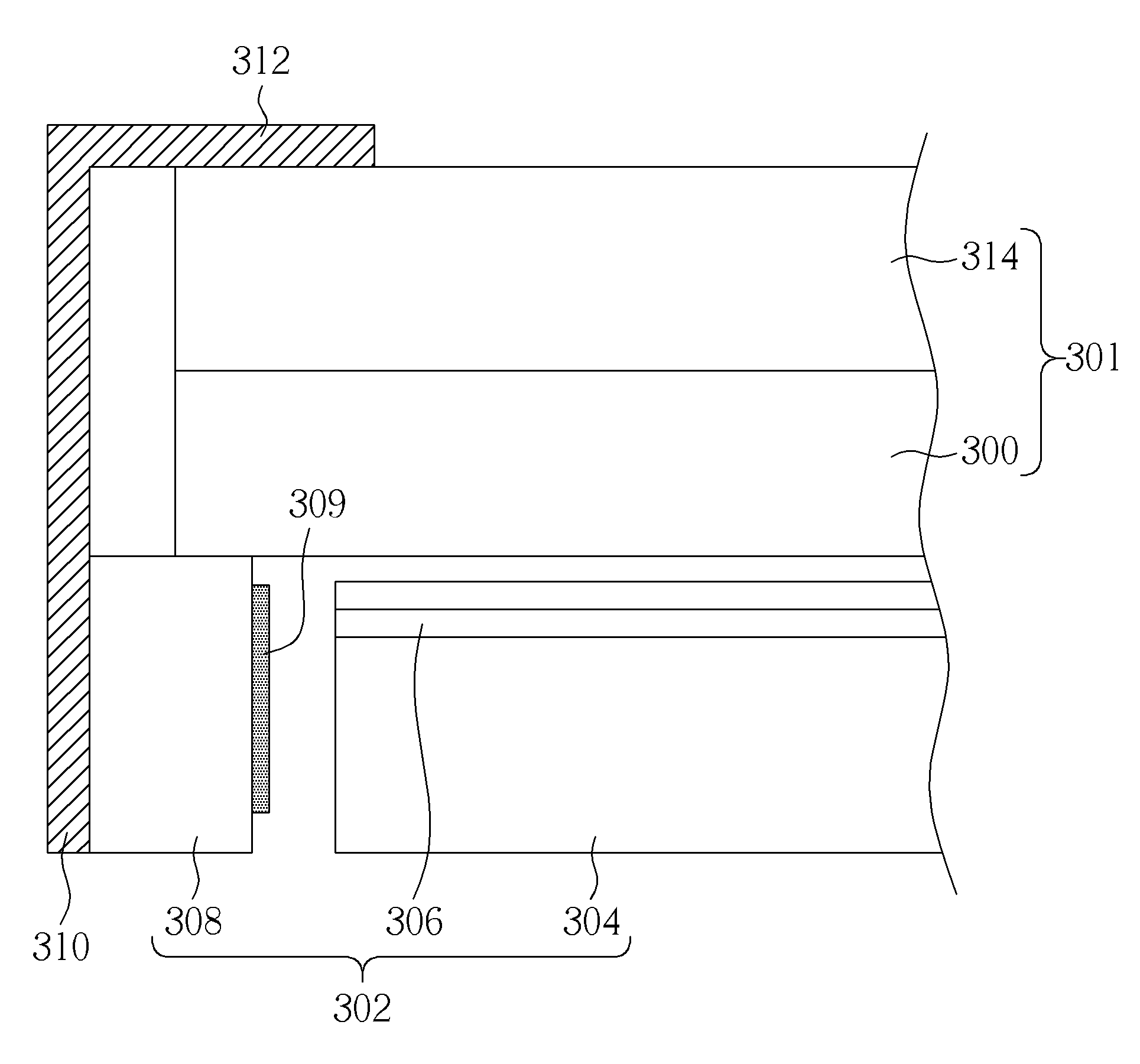
[0010]According to the claimed invention, a stereoscopic display device is provided. The stereoscopic display device includes a stereoscopic display unit, a backlight module and an outer frame. The stereoscopic display unit includes a liquid crystal display panel and a parallax barrier, wherein the LCD panel is disposed opposite to the parallax barrier. The backlight module is disposed on a side of the stereoscopic display unit. The backlight module includes a light source and a rubber frame, wherein the rubber frame is disposed on an outer side of the light source. The outer frame is disposed on an outer side of the stereoscopic display unit and the backlight module. The outer frame encompasses the stereoscopic display unit and the backlight module, wherein at least one of the rubber frame and the outer frame includes a light shielding component disposed on a side facing the light source to prevent light leakage from an edge of the stereoscopic display unit.
[0011]In the present invention, the light shielding component is disposed on the side of the rubber frame and the outer frame facing the light source, so light emitted from the light source is absorbed or scattered by the light shielding component and the light leakage problem in conventional stereoscopic display device can be avoided.

Problems solved by technology

However, in a current LCD panel, its flat two-dimensional (2D) display mode has been unable to meet the needs of the users.
Many problems that are not easy to arise in a conventional 2D LCD panel will occur.
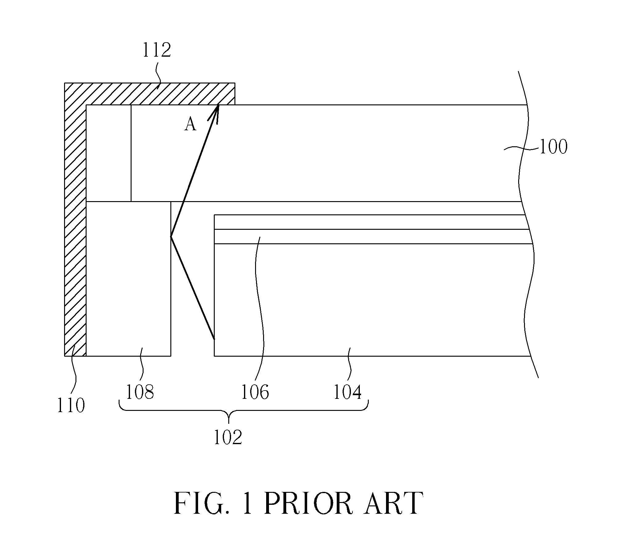
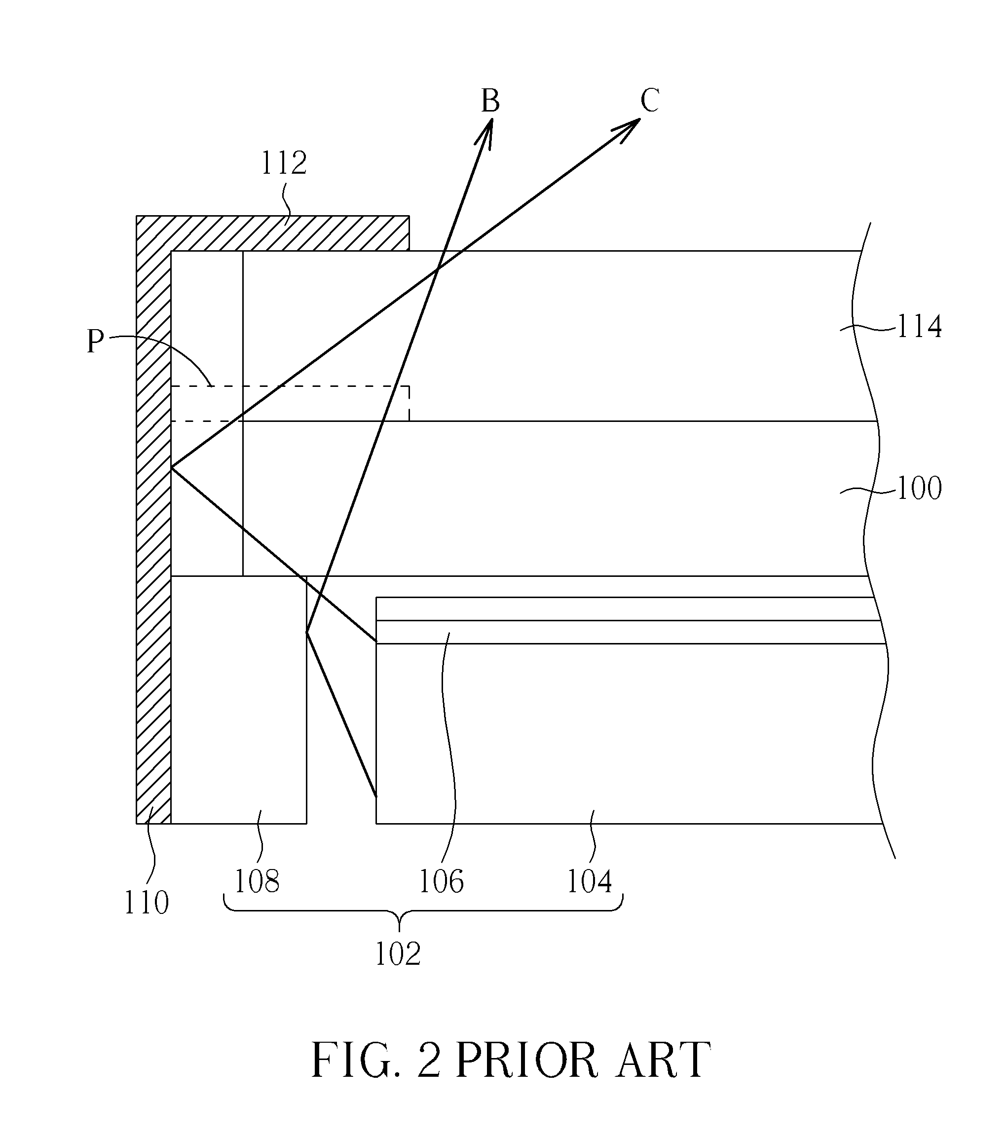
But there is still a portion of light that is irradiated on the inner side of the rubber frame 108 and reflected from the surface of the rubber frame 108, making the light pass from the edge of the LCD panel 100 into the outside environment, resulting in the light leakage phenomenon and thus impacting the display quality.
Because the outer frame 110 usually includes high reflective materials such as metals, the possibility of light refection increases as well, resulting in serious light leakage problem.

Method used


Image

  • Stereoscopic Display Device
  • Stereoscopic Display Device
  • Stereoscopic Display Device

Examples


Embodiment Construction

[0020]Certain terms are used throughout the description and following claims to refer to particular components. As one skilled in the art will appreciate, electronic equipment manufacturers may refer to a component by different names. This document does not intend to distinguish between components that differ in name but not function. In the following description and in the claims, the terms “include” and “comprise” are used in an open-ended fashion, and thus should be interpreted to mean “include, but not limited to . . . .”

[0021]Please refer to FIG. 3, illustrating a schematic diagram of the first embodiment of the stereoscopic display device in the present invention. As shown in FIG. 3, the stereoscopic display device in the present invention includes a stereoscopic display unit 301, a backlight module 302 and an outer frame 310. The stereoscopic display unit 301 includes a liquid crystal display panel 300 and a parallax barrier 314, both of which are opposite to each other and a...


PUM


Abstract

A stereoscopic display device includes a stereoscopic display unit, a backlight module and an outer frame. The stereoscopic display unit includes an LCD panel and a parallax barrier opposite to each other. The backlight module is disposed on a side of the stereoscopic display unit and includes a light source and a rubber frame, wherein the rubber frame is disposed on an outer side of the light source. The outer frame encompasses the stereoscopic display unit and the backlight module. At least one of the rubber frame and the outer frame includes a light shielding component disposed on a side facing the light source to prevent light leakage form an edge of the stereoscopic display unit.

Description

BACKGROUND OF THE INVENTION[0001]1. Field of the Invention[0002]The present invention relates to a stereoscopic display device, and more particularly to a stereoscopic display device that can prevent light leakage from the edge of the display region.[0003]2. Description of the Prior Art[0004]As the photovoltaic technology and semiconductor technology become mature in current years, various types of flat display panels have been developed vigorously. The liquid crystal display (LCD) panel that has the advantages of low-power-consumption, low-radiation, light-weight and small-size has become the most popular display product. However, in a current LCD panel, its flat two-dimensional (2D) display mode has been unable to meet the needs of the users. The research units are committed to the development of 3D display technology, hoping to make the observer perceive a 3D stereoscopic vision under a 2D display environment.[0005]The present 3D stereoscopic display technology is to use a parall...

Claims


Application Information

Patent Timeline
IPC IPC(8): G02F1/13357G02B30/25
CPCG02F1/133308G02F2001/13332G02F1/133512G02F1/13332
Inventor LEE, MING-SHULIU, CHUN-FU
Owner CHUNGHWA PICTURE TUBES LTD
Learn More