Offshore Floating Platform with Motion Damper Columns

a technology of floating platform and motion damper, which is applied in the direction of floating buildings, special-purpose vessels, transportation and packaging, etc., to achieve the effect of significant water plane area and platform stability

Inactive Publication Date: 2010-11-18
MANSOUR ALAA
View PDF4 Cites 17 Cited by
  • Summary
  • Abstract
  • Description
  • Claims
  • Application Information

AI Technical Summary

Benefits of technology

The present invention relates to an improved design for offshore platforms used for oil and gas drilling and production. These improvements involve adding special features called motion damping chambers within the support columns of the platform's hull structure. When sea waves move the platform back and forth, these chambers help reduce this movement and make the platform more stable. By doing this, the new platform can better resist damage from wind and wave action while still maintaining its ability to safely hold heavy machinery and produce energy efficiently.

Problems solved by technology

This patent discusses various types of semisubmersible platforms designed for offshore activities like drilling and producing oil and gas. These platforms have unique features such as pontoons, squarenessay rings, and other configurations to improve safety, efficiency, and performance during sea states. The technical problem addressed in this patent is how to design these platforms to minimize heaving motions while still maintaining stable operation under varying wavelengths of waves and currents.

Method used


Image

  • Offshore Floating Platform with Motion Damper Columns
  • Offshore Floating Platform with Motion Damper Columns
  • Offshore Floating Platform with Motion Damper Columns

Examples


second embodiment

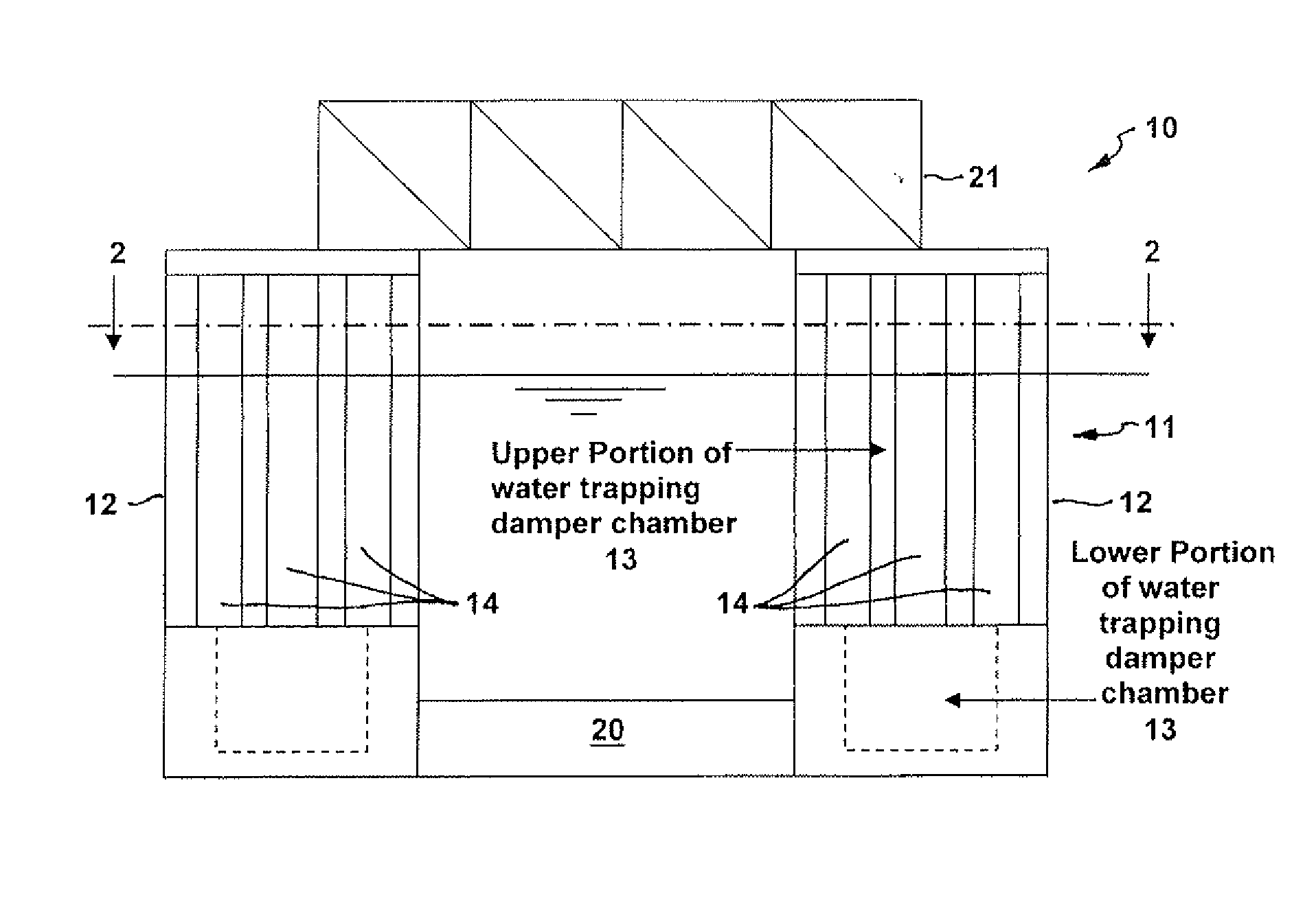
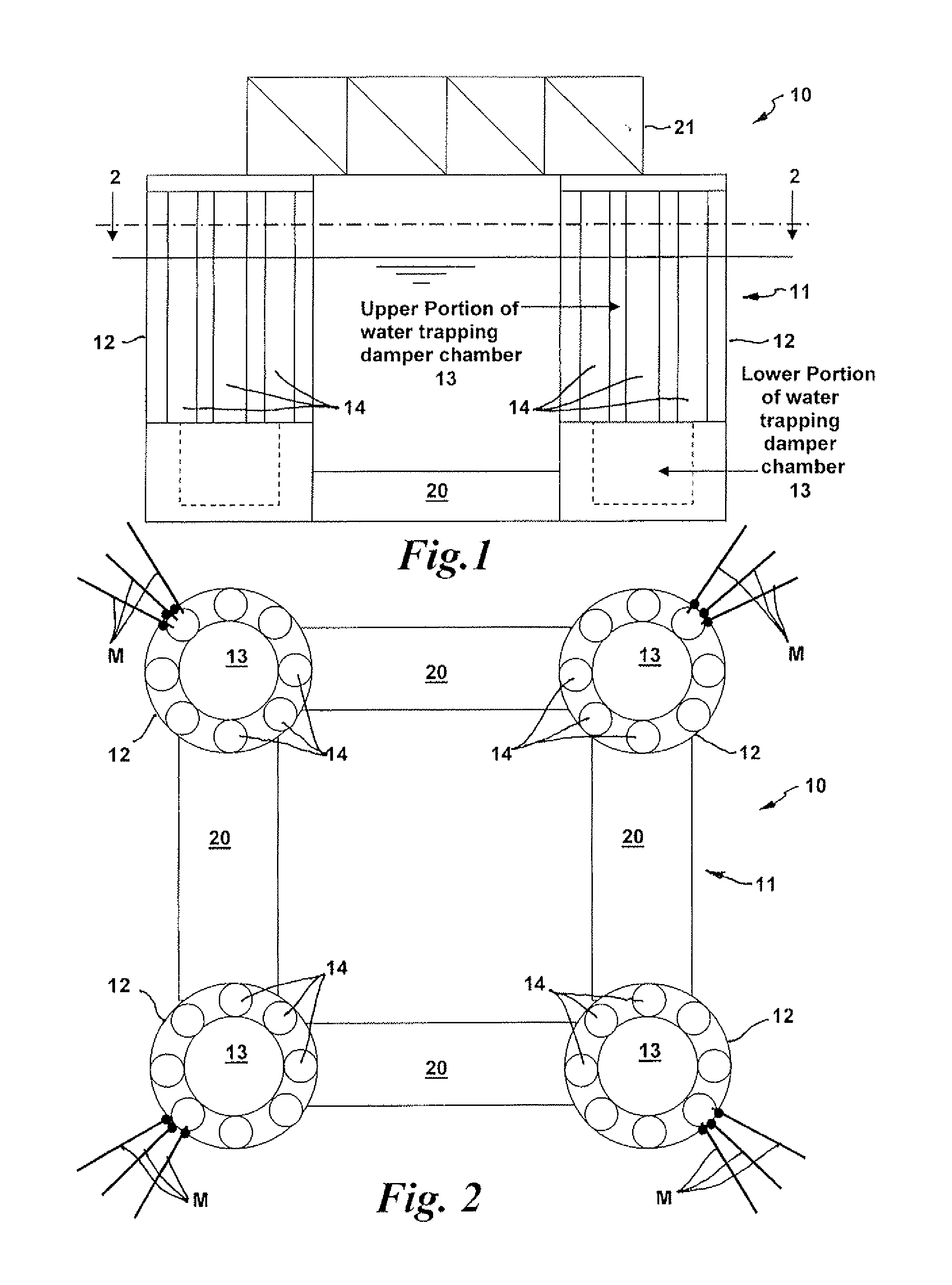
[0037]Referring now to FIGS. 5 and 6, there is shown, somewhat schematically, the semi-submersible floating platform 10A with cylindrical motion damping support columns 14 having a cylindrical inner water trapping damper chamber 13 and a plurality of generally wedge-shaped columns or chambers arranged on the perimeter of the support columns in circumferentially adjacent relation. The components that are the same as described above in the previous embodiment are assigned the same numerals of reference, but will not be described again in detail to avoid repetition.

third embodiment

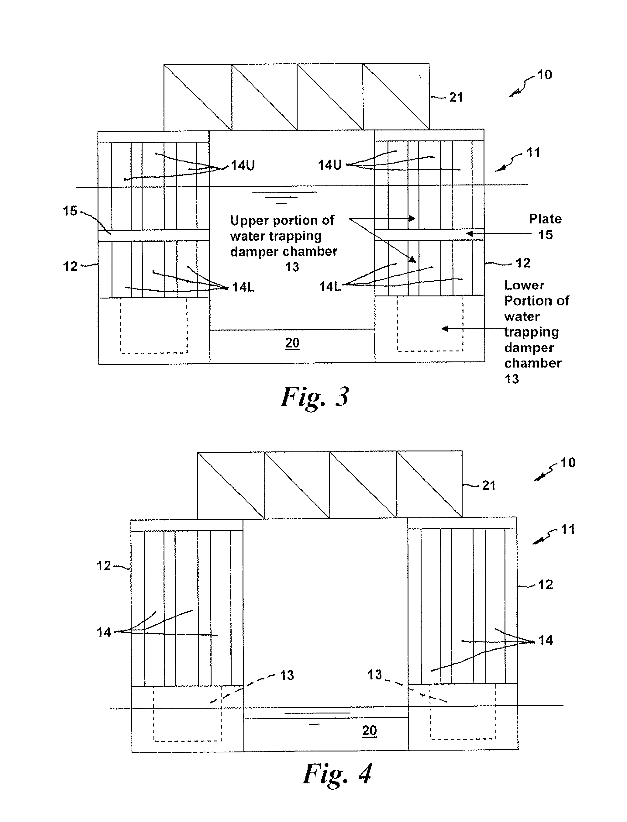
[0038]FIGS. 7 and 8 show, somewhat schematically, the semi-submersible floating platform 10B having generally rectangular motion damping support columns 12A and a generally rectangular inner water trapping damper chamber 13A. In this embodiment, a plurality of smaller cylindrical columns 14 are disposed on the perimeter of the generally rectangular support columns 12A in adjacent spaced apart relation. The components that are the same as described above in the previous embodiments are assigned the same numerals of reference, but will not be described again in detail to avoid repetition.

fourth embodiment

[0039]FIGS. 9 and 10 show, somewhat schematically, the semi-submersible floating platform 10C having generally rectangular motion damping support columns 12A, each having a generally rectangular inner water trapping damper chamber 13A. In this embodiment, a plurality of smaller generally rectangular columns 14B disposed on the perimeter of the generally rectangular support columns 12A in adjacent relation. The components that are the same as described above in the previous embodiments are assigned the same numerals of reference, but will not be described again in detail to avoid repetition.


PUM


Abstract

A semi-submersible floating platform for use in offshore applications having a semi-submersible hull structure including motion damping support columns, a pontoon structure adjoined to the motion damping support columns at a lower end thereof, and a deck structure supported at an upper end of thereof for supporting equipment mounted thereon above the water surface. Each motion damping support column has an inner water trapping damper chamber of closed base or open base construction that allows natural flooding of said inner water trapping damper chamber during installation and before reaching an operating draft of the platform, and which when flooded provides hydrodynamic mass, damping, and in-water weight to said platform during operation. A plurality of smaller columns are disposed on the perimeter of the upper portion of each support column and surround the upper portion of the inner water trapping damper chamber.

Description


Claims


Application Information

Patent Timeline
Owner MANSOUR ALAA
Why Eureka
Try Eureka