
Comb-type electrode structure capable of large linear-displacement motion

a comb-type electrode and linear displacement technology, applied in the field of vertical comb-type electrode structures, can solve the problems of not being able to provide a linear motion at an applied voltage less than the threshold value, accompanied by a significantly non-linear motion, and the vertical comb-type electrode structure of fig. 4a cannot provide a large displacement, so as to achieve a large linear displacement

Inactive Publication Date: 2007-06-21
SAMSUNG ELECTRONICS CO LTD
View PDF3 Cites 1 Cited by
  • Summary
  • Abstract
  • Description
  • Claims
  • Application Information

AI Technical Summary

Benefits of technology

[0012] The present invention provides a simple vertical comb-type electrode structure that provides a large linear displacement motion.

Problems solved by technology

However, when a large displacement in a conventional vertical comb-type electrode structure occurs, it is accompanied by a significantly non-linear motion.
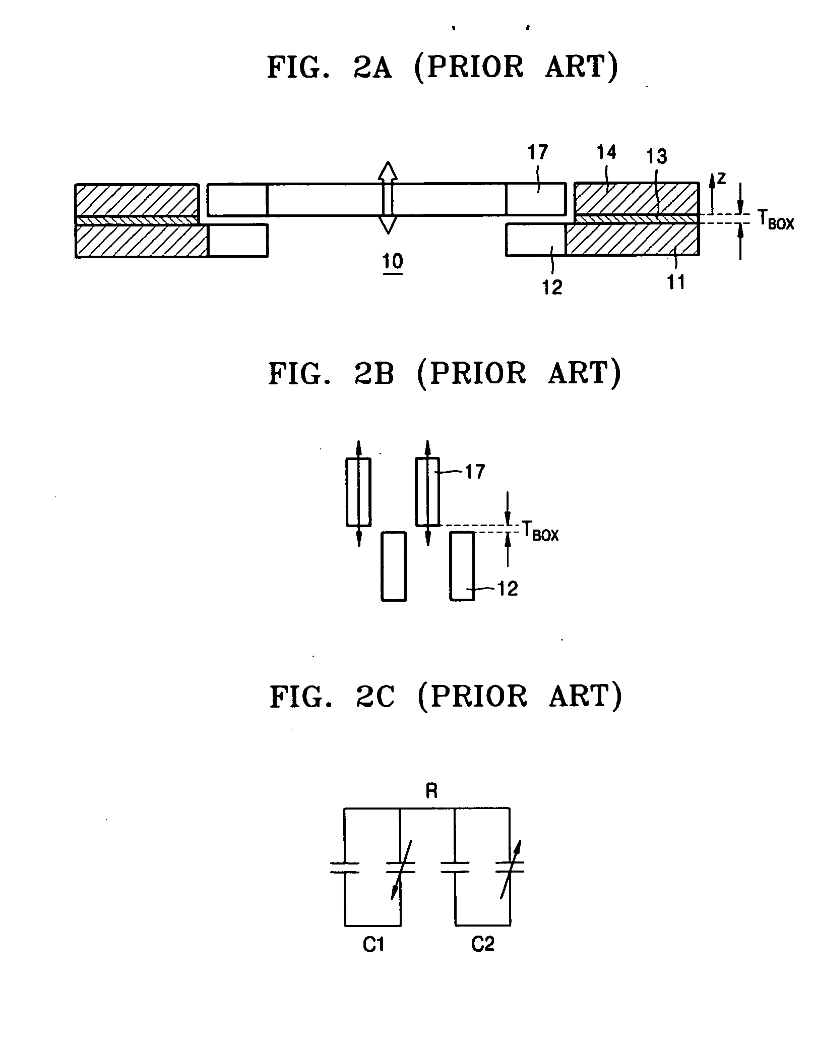
Accordingly, the two-layered vertical comb-type electrode structure of FIG. 2A can provide a relatively large displacement, but cannot provide a linear motion at an applied voltage less than the threshold value.
Accordingly, the vertical comb-type electrode structure of FIG. 4A cannot provide a large displacement.

Method used


Image

  • Comb-type electrode structure capable of large linear-displacement motion
  • Comb-type electrode structure capable of large linear-displacement motion
  • Comb-type electrode structure capable of large linear-displacement motion

Examples


Embodiment Construction

[0039] Hereinafter, the present invention will be described more fully with reference to the accompanying drawings, in which exemplary embodiments of the invention are shown.

[0040]FIG. 6A is a cross-sectional view of a vertical comb-type electrode structure that vertically moves, according to an embodiment of the present invention. Referring to FIG. 6A, a silicon-on-insulator (SOI) substrate including a lower silicon substrate 21 and an upper silicon substrate 24 is bonded to a base substrate 30. The bonding method is, for example, an anodic bonding method, a silicon direct bonding (SDB) method, or a metallic bonding method. Like the conventional art, an insulation layer 23, for example, an oxide layer, is interposed between the lower silicon substrate 21 and the upper silicon substrate 24 so that electric shorts between the lower silicon substrate 21 and the upper silicon substrate 24 are prevented. A plurality of vertical static comb-electrodes 22 are integrally formed with the l...


PUM


Abstract

A vertical comb-type electrode structure capable of a large linear-displacement motion. The vertical comb-electrode structure includes: a first substrate including a plurality of vertical static comb-electrodes; and a second substrate stacked on an upper surface of the first substrate, the second substrate including a plurality of vertical moving comb-electrodes, wherein the static comb-electrodes are vertically moved or positioned a predetermined distance toward the moving comb-electrodes in the initial state of the electrode structure so that no gaps between the static comb-electrodes and the moving comb-electrodes exist.

Description

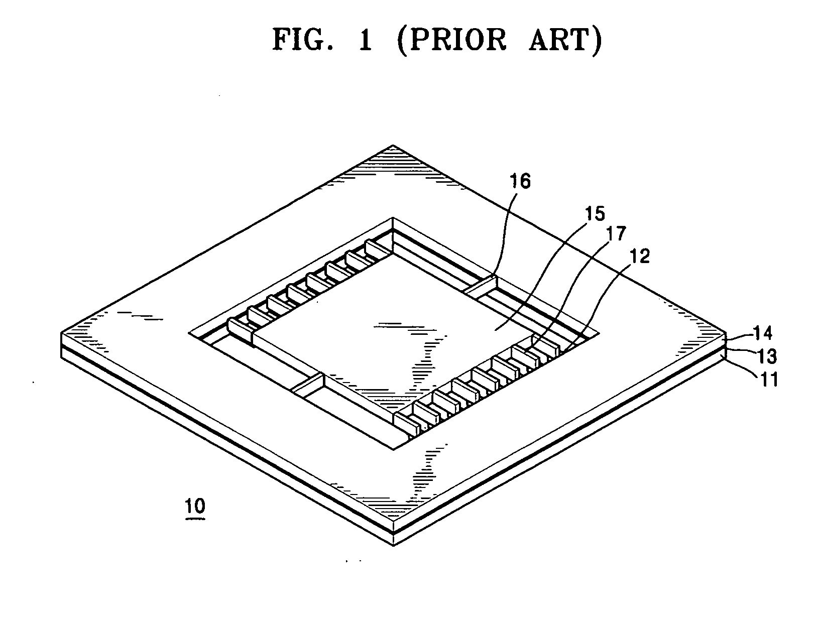
CROSS-REFERENCE TO RELATED PATENT APPLICATION [0001] This application claims the benefit of Korean Patent Application No. 10-2005-0125454, filed on Dec. 19, 2005, in the Korean Intellectual Property Office, the disclosure of which is incorporated herein in its entirety by reference. BACKGROUND OF THE INVENTION [0002] 1. Field of the Invention [0003] The present invention relates to a vertical comb-type electrode structure provided by a micro-electromechanical system (MEMS) technique, and more particularly, to a vertical comb-type electrode structure which can perform a large linear-displacement motion. [0004] 2. Description of the Related Art [0005] Vertical comb-type electrode structures in which moving comb-electrodes (or a rotor) and static comb-electrodes (or a stator) are formed on a silicon-on-insulator (SOI) substrate are generally used in electrostatic sensors, micro light scanners, or microactuators. [0006]FIG. 1 is a perspective view of a conventional vertical comb-type el...

Claims


Application Information

Patent Timeline
IPC IPC(8): G02F1/1343
CPCB81B3/0037B81B2201/033B81B2201/047B81B2203/0136B81B2203/04B81B7/02B81B7/00B81C1/00B81B5/00
Inventor LEE, BYEUNG-IEUL
Owner SAMSUNG ELECTRONICS CO LTD
Learn More