Supercharge Your Innovation With Domain-Expert AI Agents!

Syringe Assembly

a technology of syringes and syringes, which is applied in the field of syringe assemblies, can solve the problems of blood entering the catheter line, the syringe stops expanding,

Inactive Publication Date: 2010-11-18
BECTON DICKINSON & CO
View PDF23 Cites 0 Cited by
  • Summary
  • Abstract
  • Description
  • Claims
  • Application Information

AI Technical Summary

Benefits of technology

The solution reduces fluid pressure by one-third compared to smaller syringe assemblies, making it easier to detect catheter occlusions and preventing catheter damage, while minimizing blood reflux and simplifying manufacturing.

Problems solved by technology

Unfortunately, during the flushing of vascular access devices, different nominal size syringes generate substantially different pressures in the solution being injected by the same force being applied to the syringe plunger rod.
When using a syringe with an elastomeric stopper, if the stopper is compressed by action of the plunger rod, release of the plunger rod causes the stopper to expand and may cause blood to enter the catheter line.

Method used


Image

  • Syringe Assembly
  • Syringe Assembly
  • Syringe Assembly

Examples


Embodiment Construction

[0020]While this invention is satisfied by embodiments in many different forms, there are shown in the drawings and will herein be described in detail, preferred embodiments of the invention with the understanding that the present disclosure is to be considered exemplary of the principles of the invention and not intended to limit the invention to the embodiments illustrated. The scope of the invention will be measured by the appended claims and their equivalents.

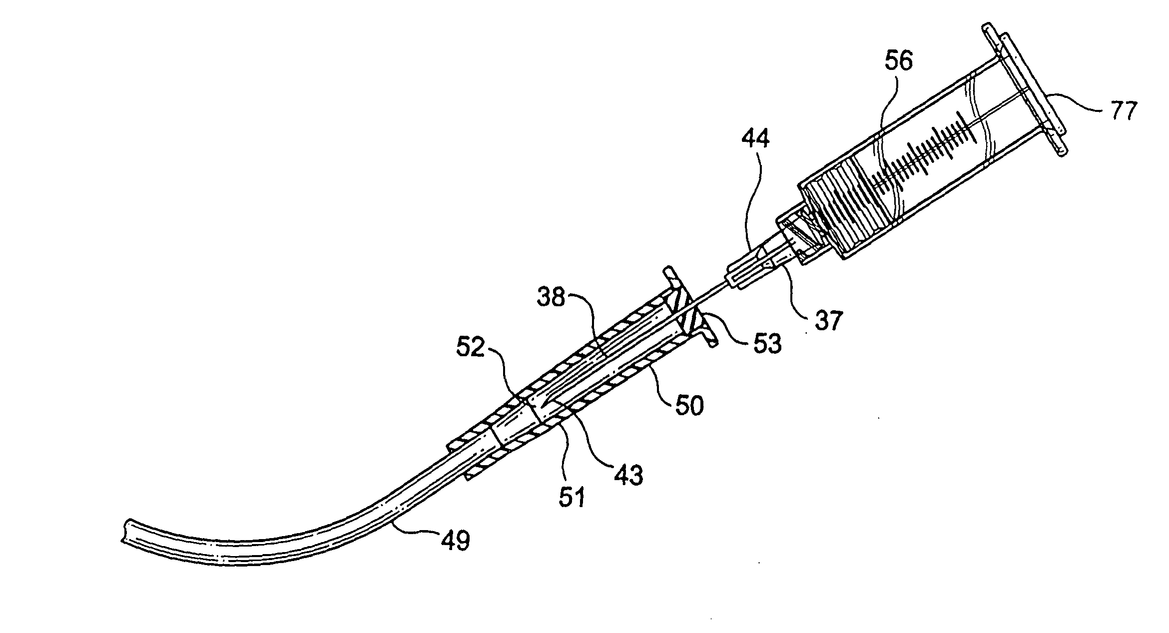
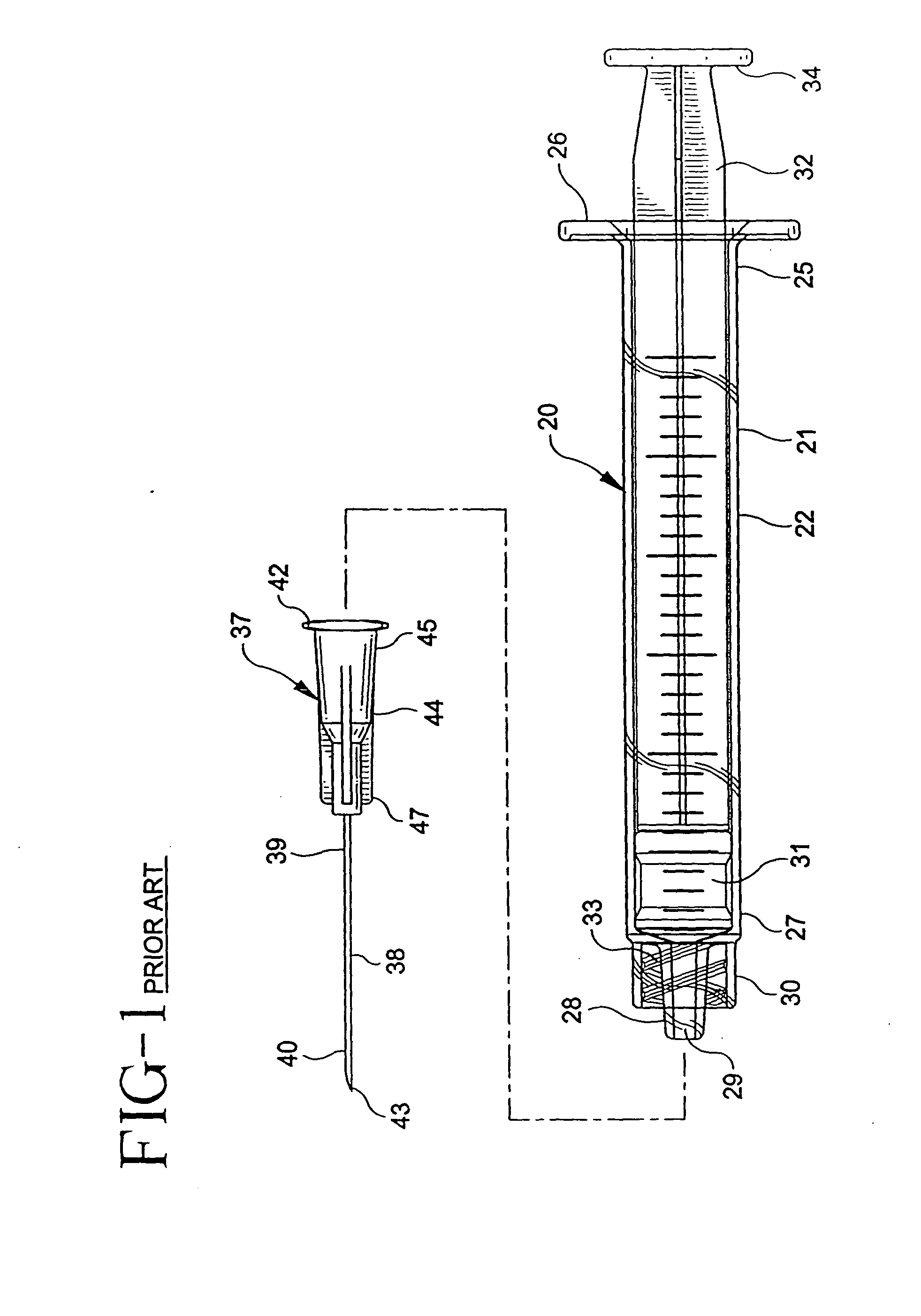
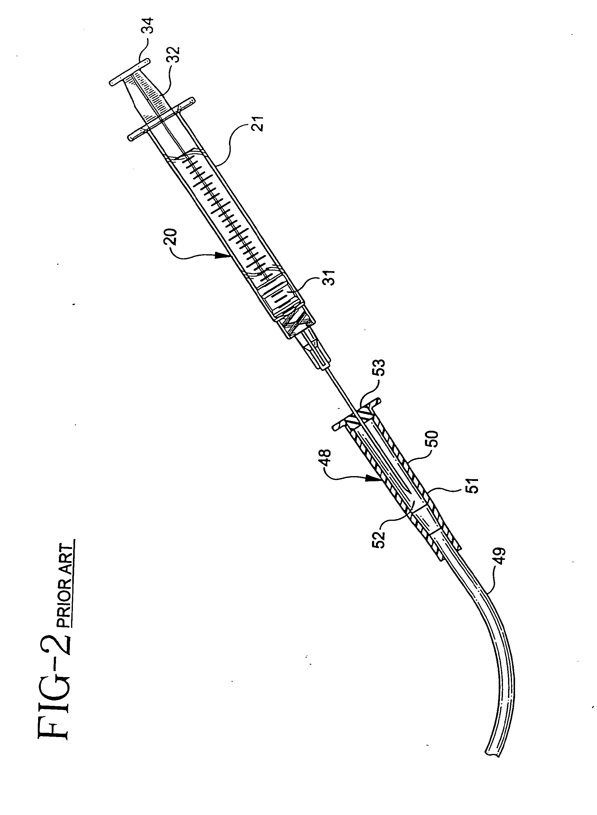
[0021]Adverting to FIGS. 1-7, prior art syringe assembly 20 includes a barrel 21 having an elongate body 22 defining a chamber 23 for retaining fluid. The barrel includes an open proximal end 25 having a flange 26 and a distal end 27 including a tip 28 having a passageway 29 therethrough in fluid communication with the chamber. The distal end of the barrel also preferably, but not necessarily, includes a locking luer-type collar30 concentrically surrounding tip 28. The luer collar has an internal thread 33.

[0022]A prior art...


PUM


Abstract

A syringe assembly comprises a syringe barrel having an elongated body defining a chamber for retaining fluid, an open proximal end, a distal end and a frusto-conically shaped tip extending from the distal end and having a passageway therethrough in fluid communication with the chamber. The chamber has an inside diameter of at least 13.5 mm. A stopper is in fluid-tight engagement inside the barrel. An elongated plunger rod extends proximally from the stopper through the open proximal end of the barrel. A flange is positioned at the proximal end of the plunger rod. The flange is shaped and positioned to limit the distal motion of the plunger rod in the barrel by contacting the proximal end of the barrel. A tip cap is releasably connected to the tip for sealing the passageway and the chamber contains injectable liquid.

Description

CROSS-REFERENCE TO RELATED APPLICATIONS[0001]This is a continuation of U.S. patent application Ser. No. 12 / 684,189, filed on Jan. 8, 2010, which is a division of U.S. patent application Ser. No. 10 / 727,194, filed on Dec. 3, 2003, now U.S. Pat. No. 7,682,342, issued Mar. 23, 2010, which is a continuation of U.S. patent application Ser. No. 10 / 067,166, filed on Feb. 4, 2002, now abandoned, which is a continuation of U.S. patent application Ser. No. 09 / 060,117, filed on Apr. 14, 1998, now U.S. Pat. No. 6,361,524, issued Mar. 26, 2002.BACKGROUND OF THE INVENTION[0002]The present invention relates to syringe assemblies and more particularly concerns syringe assemblies for use in I.V. flush procedures.[0003]An I.V. catheter is a commonly used therapeutic device. Many patients, in accordance with their therapy, have an I.V. catheter connected to a vein ready for use in various procedures or in fluid communication with an I.V. system for infusing liquids and medication. Many I.V. sets have ...

Claims


Application Information

Patent Timeline
Patent Type & Authority Applications(United States)
IPC IPC(8): A61M5/315A61B19/02A61M5/178A61M5/00A61M5/31A61M5/34A61M5/50
CPCA61M5/002A61M5/3129A61M5/31525A61M2005/3104A61M5/347A61M5/5086A61M5/31535
Inventor ODELL, ROBERT B.ZACH, LAWRENCE J.WALLACE, ALEX S.
Owner BECTON DICKINSON & CO
Features
  • R&D
  • Intellectual Property
  • Life Sciences
  • Materials
  • Tech Scout
  • Unparalleled Data Quality
  • Higher Quality Content
  • 60% Fewer Hallucinations
Learn More