
Apparatus for electronically controllable transmission

a technology of electronic control and transmission device, applied in the direction of mechanical control device, process and machine control, instruments, etc., can solve the problems of increasing the size of the sensor unit, increasing the cost of the related device, and reducing the utilization of layout, so as to achieve the effect of easy position detection

Active Publication Date: 2010-11-25
SL CORP
View PDF6 Cites 32 Cited by
  • Summary
  • Abstract
  • Description
  • Claims
  • Application Information

AI Technical Summary

Benefits of technology

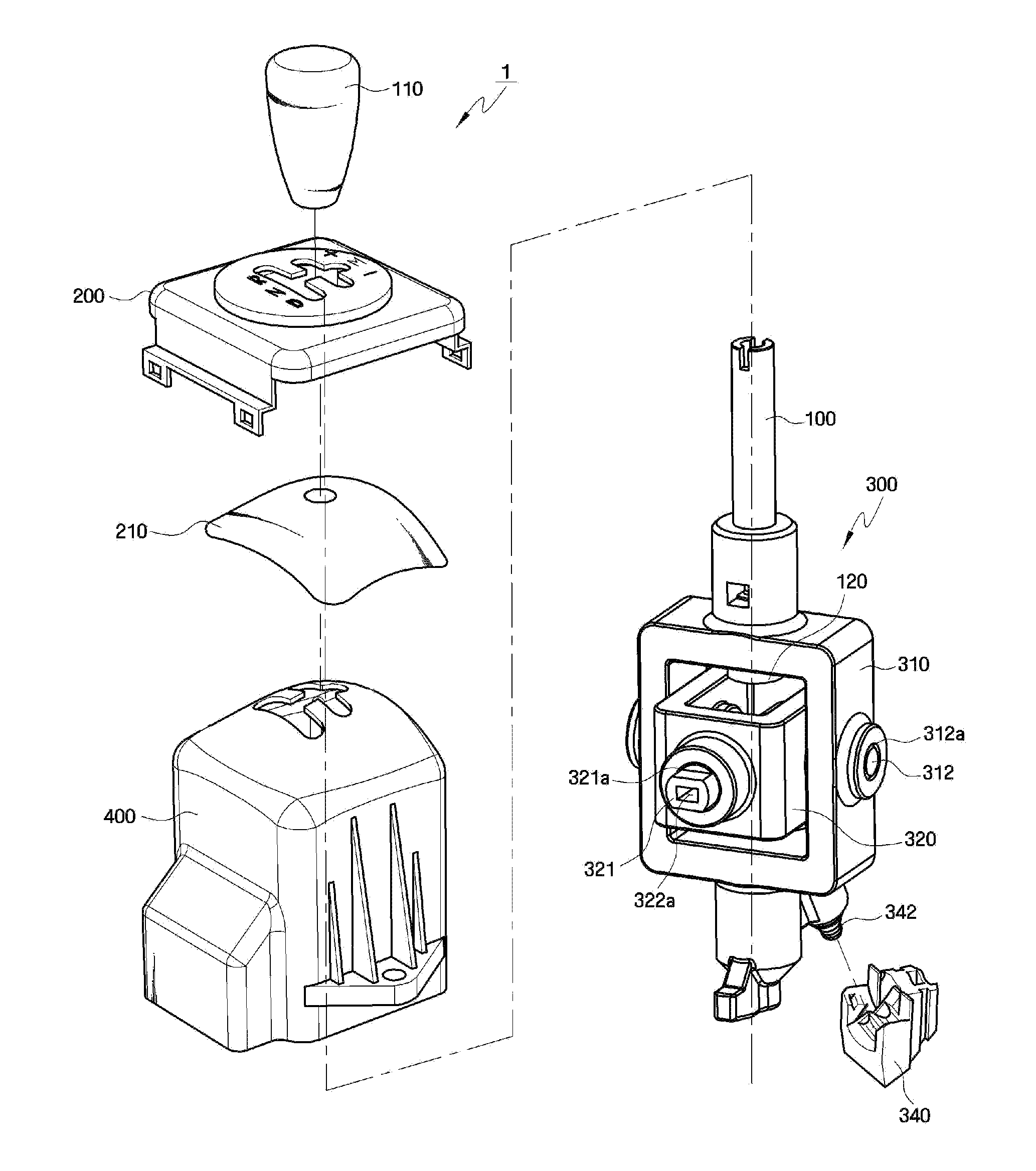
[0016]Aspects of the present invention provide an apparatus for electronically controllable transmission, the apparatus capable of easily sensing the position of a shift lever using one sensor and detecting a gear desired by a driver even without maintaining a constant gap between a magnet and the sensor.
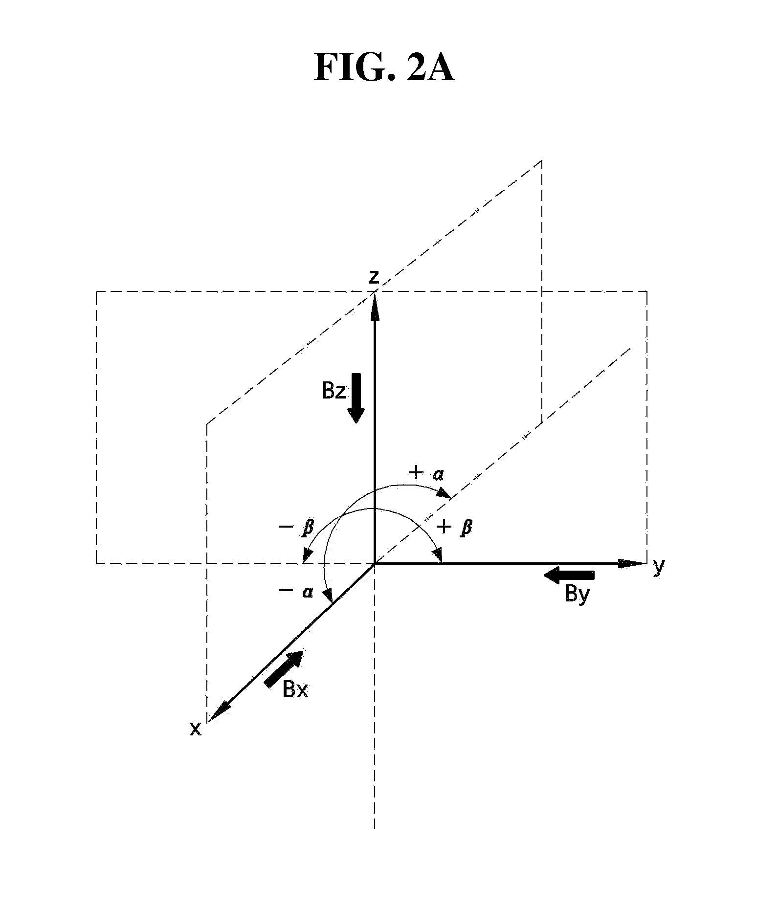
[0018]Aspects of the present invention also provide an apparatus for electronically controllable transmission, the apparatus capable of sensing the position of a shift lever in a stable manner by having a 3D sensor turned at a predetermined angle so that at least some of X-, Y- and Z-axis signals can be generated linearly when a magnet moves in one direction.

Problems solved by technology

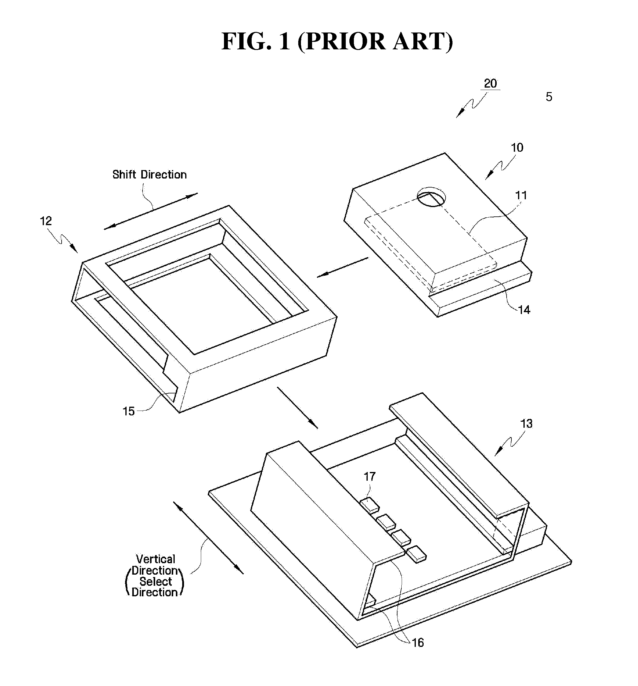
However, the conventional 2D hall sensor requires a plurality of sensors for each gear and must maintain a constant gap between itself and the magnet.
Accordingly, the increased number of such structures increases the size of a sensor unit, reduces layout utilization, and raises related costs.

Method used


Image

  • Apparatus for electronically controllable transmission
  • Apparatus for electronically controllable transmission
  • Apparatus for electronically controllable transmission

Examples


Embodiment Construction

[0034]Advantages and features of the present invention and methods of accomplishing the same may be understood more readily by reference to the following detailed description of exemplary embodiments and the accompanying drawings. The present invention may, however, be embodied in many different forms and should not be construed as being limited to the embodiments set forth herein. Rather, these embodiments are provided so that this disclosure will be thorough and complete and will fully convey the concept of the invention to those skilled in the art, and the present invention will only be defined by the appended claims. Like reference numerals refer to like elements throughout the specification.

[0035]In some embodiments, well-known processes, structures, and technologies will not be specifically described in order to avoid ambiguous interpretation of the present invention.

[0036]The terminology used herein is for the purpose of describing particular embodiments only and is not inten...


PUM


Abstract

Provided is an apparatus for electronically controllable transmission, and more particularly, an apparatus for electronically controllable transmission, the apparatus capable of shifting gears by moving a shift lever and sensing the magnetic flux density of a magnet, which moves in accordance with the rotation of the shift lever, by using a three-dimensional (3D) hall sensor. The apparatus includes: a shift lever including one end which is connected to a magnet and shifting gears by moving the shift lever; a shift lever body which is connected to the shift lever and is allowing the shift lever to move around shift axis or select axis; and a sensor unit including a 3D sensor which is mounted fixedly in the place intersecting the shift axis and select axis within the shift lever body and can sense the movement of the magnet around an X-axis, a Y-axis and a Z-axis as the magnet moves, wherein the 3D sensor is mounted at a tilted angle for providing at least two of three output signals with linearity.

Description

[0001]This application claims priority from Korean Patent Application No. 10-2009-0044106 filed on May 20, 2009 in the Korean Intellectual Property Office, the disclosure of which is incorporated herein by reference in its entirety.BACKGROUND OF THE INVENTION[0002]1. Field of the Invention[0003]The present invention relates to an apparatus for electronically controllable transmission, and more particularly, to an apparatus for electronically controllable transmission, the apparatus capable of shifting gears by sensing the magnetic flux density of a magnet as the magnet connected to a shift lever moves.[0004]2. Description of the Related Art[0005]Vehicle transmissions change gear ratios to maintain the torque of an engine constant according to the speed of a vehicle. To change the gear ratios of a transmission, a shift lever of the transmission may be operated. Generally, there are two types of transmissions. One is a manual mode transmission that allows a user to manually shift gear...

Claims


Application Information

Patent Timeline
Patent Type & Authority Applications(United States)
IPC IPC(8): F16H59/04
CPCF16H59/0204F16H59/044Y10T74/2003Y10T74/20116F16H2059/0273B60K20/02F16H59/10
Inventor BAK, JEONG-HOKIM, BYUNG-KI
Owner SL CORP
Learn More