Wind-powered electricity generator

a wind-powered electricity generator and generator blade technology, which is applied in the direction of electric generator control, renewable energy generation, greenhouse gas reduction, etc., can solve the problems of wind power not being stable, and the blades of conventional wind-powered electricity generators may be broken in a stiff wind condition, so as to achieve safe power generation

Inactive Publication Date: 2010-11-25
LIAO FU CHANG
View PDF17 Cites 4 Cited by
  • Summary
  • Abstract
  • Description
  • Claims
  • Application Information

AI Technical Summary

Benefits of technology

[0006]The main objective of the present invention is to provide a wind-powered electricity generator that can generate power safely.

Problems solved by technology

However, the wind-power is not stable and is depended on the weather and the conventional wind-powered electricity generator can not generate power in a slight wind condition and the blades of the conventional wind-powered electricity generator may be broken in a stiff wind condition.

Method used


Image

  • Wind-powered electricity generator
  • Wind-powered electricity generator
  • Wind-powered electricity generator

Examples


first embodiment

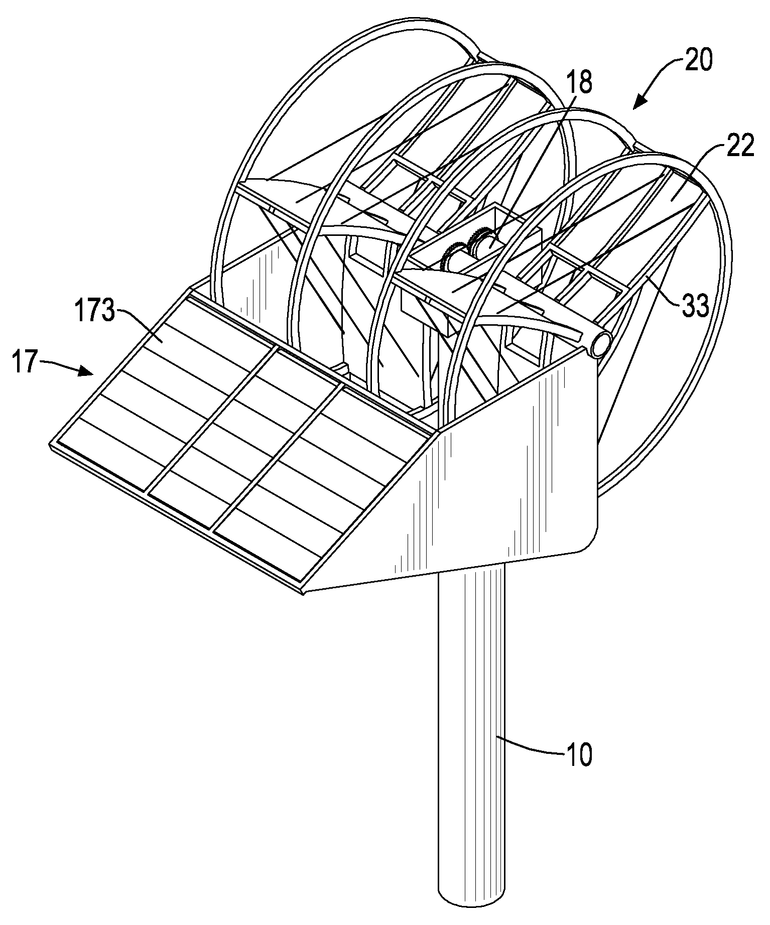
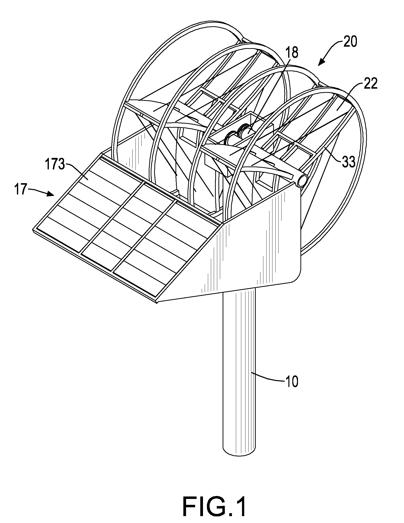
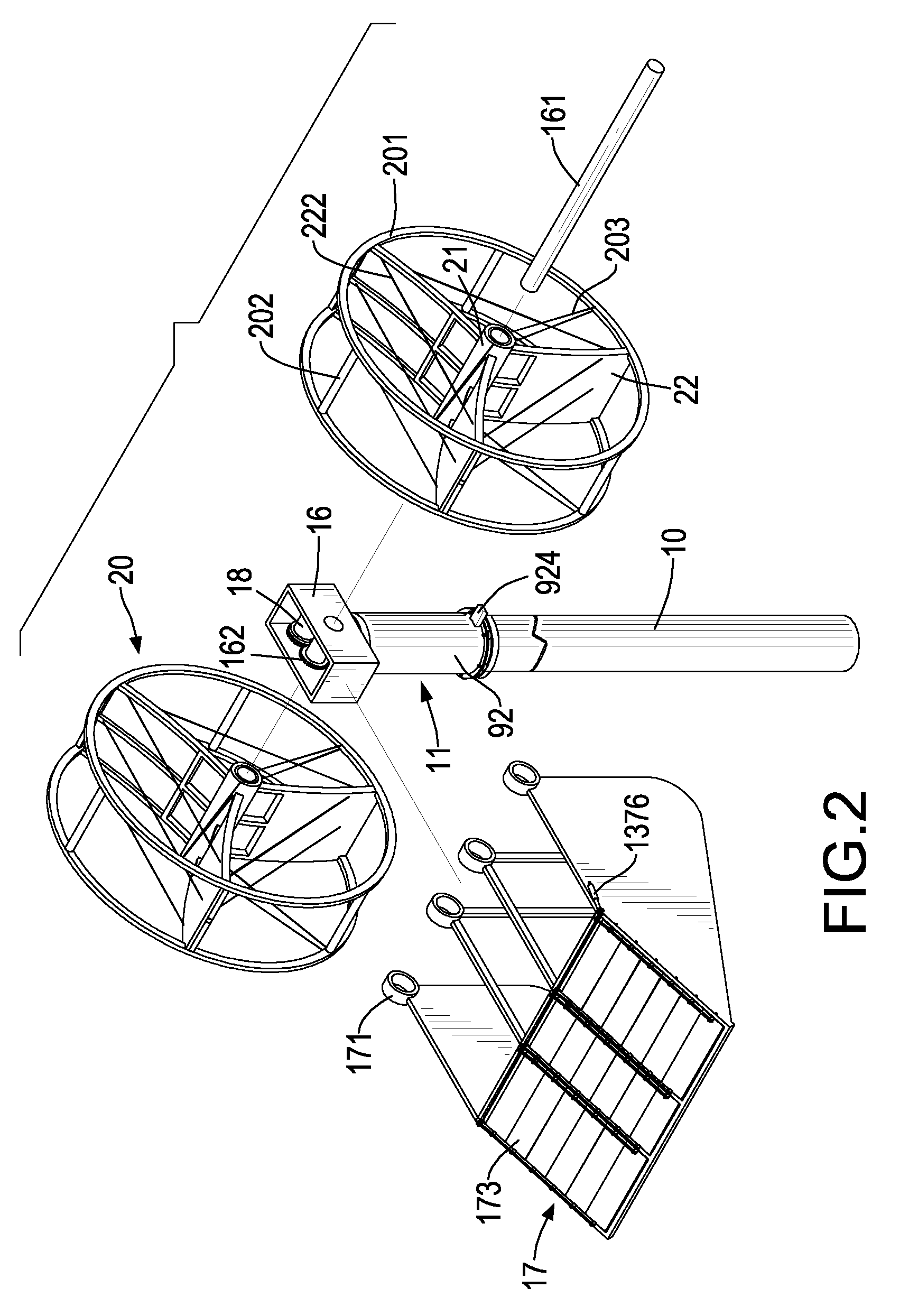
[0025]With reference to FIGS. 1 and 2, a wind-powered electricity generator in accordance with the present invention comprises a supporting tube (10), a rotating device (11), a drive device (80), a mounting frame (16), a guiding board (17) and two fan bodies (20).

[0026]With reference to FIGS. 10 and 11, the supporting tube (10) is mounted on a fixture to provide a supporting effect, may be hollow and has an external surface, an open top end, a track (910) and a shaft mount (911). The track (910) is formed around the external surface of the supporting tube (10) near the open top end. The shaft mount (911) is securely mounted in the open top end of the supporting tube (10) by fasteners and has two bearings (912, 913).

[0027]The rotating device (11) is rotatably mounted on the supporting tube (10) and has a mounting tube (92), a top cover (93) and a transmitting shaft (95). The mounting tube (92) is hollow, is mounted around the supporting tube (10) and has a lower end, an upper end, an...

second embodiment

[0039]With reference to FIGS. 6 and 7, in the blade (22b), at least one space (31b) defined between the connecting tubes (33b) of the holding frame and the blade (22b) has at least one guiding rail (52b), at least one movable board (23b) and two expansion devices (54b).

[0040]The at least guiding rail (52b) is mounted on one of the opposite connecting tubes (33b) of the holding frame. The at least one movable board (23b) is movably mounted in the at least one space (31b), is connected to the at least guiding rail (52b) and each movable board (23b) has a top side, a bottom side and two guiding flanges (53b). The guiding flanges (53b) are respectively formed on the top side and the bottom side of the movable board (23b). Preferably, the blade (22b) has three guiding rails (52b) parallel with each other and three movable boards (23b) are respectively connected to the guiding rails (52b). One of the movable boards (23b) has multiple connecting wings (55b) and multiple fasteners (551b). T...


PUM


Abstract

A wind-powered electricity generator has a supporting tube, a rotating device, a drive device, a mounting frame, a guiding board and two fan bodies. The rotating device is rotatably mounted on the supporting tube and has a mounting tube, a top cover and a transmitting shaft. The drive device is mounted in the supporting tube and is connected to the transmitting shaft. The mounting frame is securely mounted on the mounting tube and has a spindle, a gear wheel and a dynamo. The guiding board is connected to the mounting frame, faces the wind in used and has multiple spindle rings, multiple pivotal panels, multiple linking arms, a driving shaft and an expansion device. The fan bodies are rotatably mounted around the spindle in the guiding board and each fan body has a central axle, multiple connecting tubes, multiple blades, two annular frames, multiple cross bars and multiple pull bars.

Description

BACKGROUND OF THE INVENTION[0001]1. Field of the Invention[0002]The present invention relates to a wind-powered electricity generator, and more particularly to a wind-powered electricity generator that can generate power safely.[0003]2. Description of Related Art[0004]The conventional wind-powered electricity generators have multiple blades to rotate to generate power. However, the wind-power is not stable and is depended on the weather and the conventional wind-powered electricity generator can not generate power in a slight wind condition and the blades of the conventional wind-powered electricity generator may be broken in a stiff wind condition.[0005]The wind-powered electricity generator in accordance with the present invention mitigates or obviates the aforementioned problems.SUMMARY OF THE INVENTION[0006]The main objective of the present invention is to provide a wind-powered electricity generator that can generate power safely.[0007]The wind-powered electricity generator in ...

Claims


Application Information

Patent Timeline
Patent Type & Authority Applications(United States)
IPC IPC(8): F03D9/00F03D11/00
CPCF03D3/002Y02E10/74F05B2240/40F03D3/0454Y02E10/728F03D3/02F03D3/0472F03D7/06F03D13/20F03D9/25F03D13/10F03D80/70
Inventor LIAO, FU-CHANG
Owner LIAO FU CHANG
Why Eureka
Try Eureka