

Exit Pupil Expanders with Wide Field-of-View
a wide field of view and expander technology, applied in the field can solve the problems of inconvenient material availability, limited field of view of exit pupil expanders (epes) used with near-to-eye displays (neds),
- Summary
- Abstract
- Description
- Claims
- Application Information
AI Technical Summary
Benefits of technology
Problems solved by technology
Method used
Image

Examples
Embodiment Construction
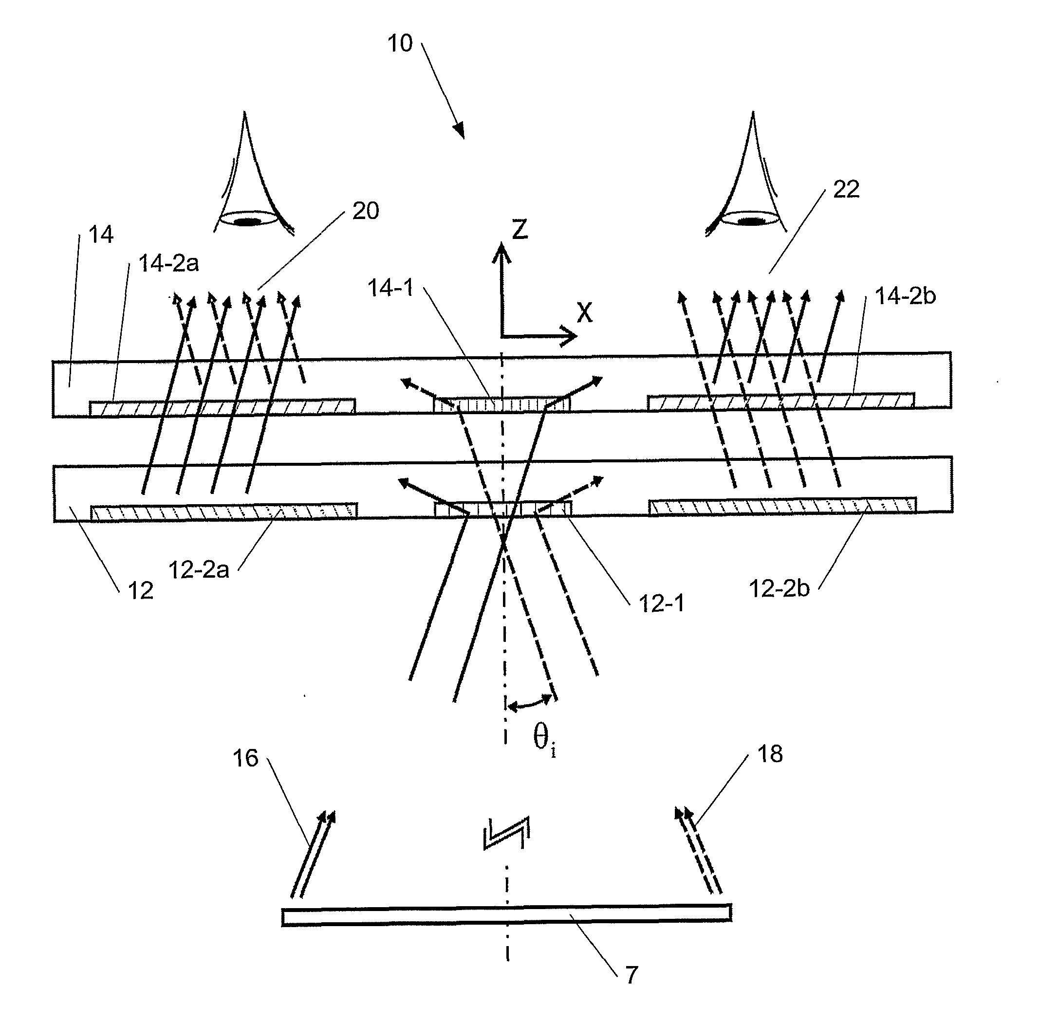
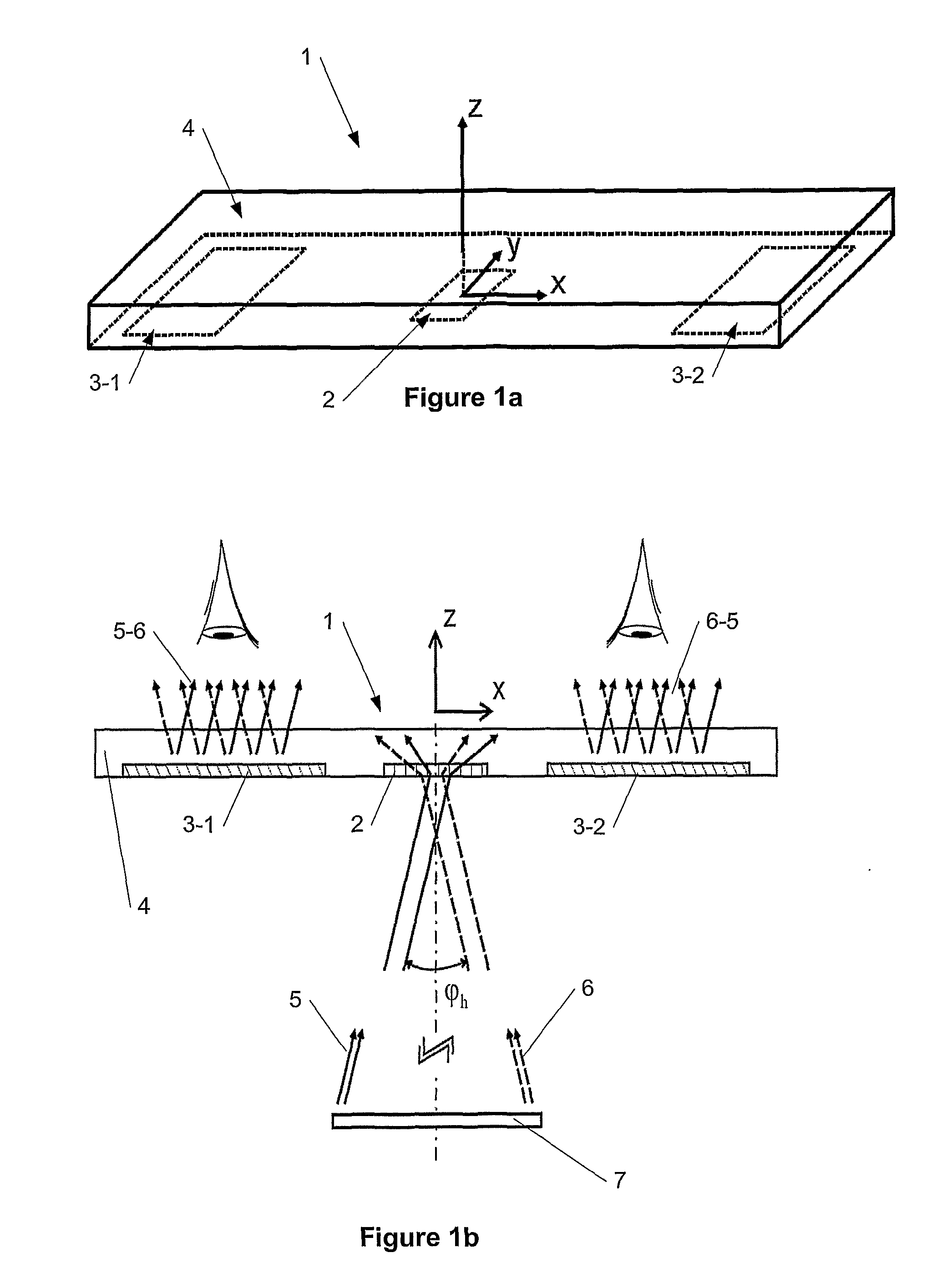
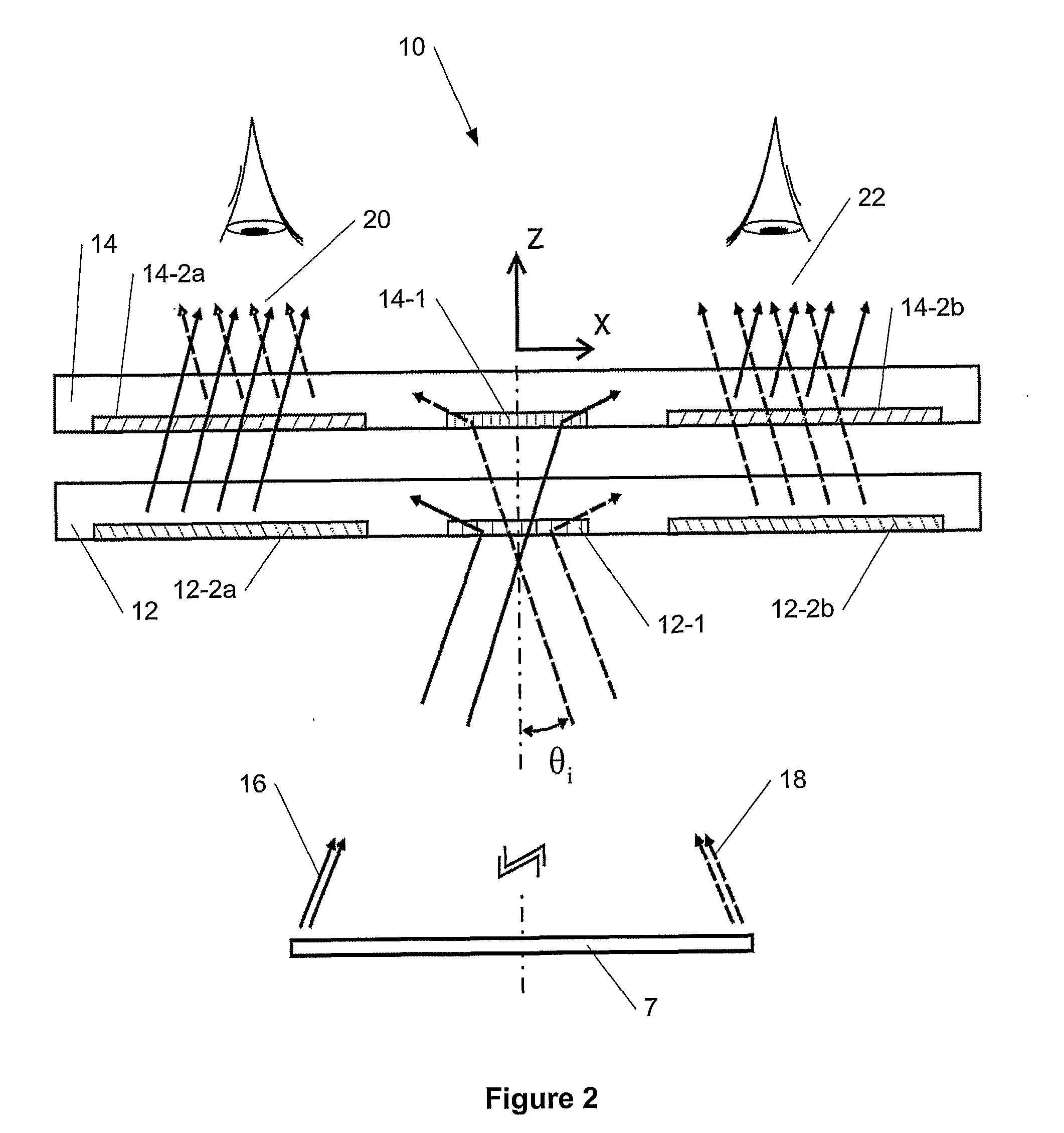
[0040]A new method and apparatus are presented for providing a wide field-of-view as well as for improving illumination uniformity in Exit Pupil Expanders (EPE) using stacked EPE substrates (or plates) with non-symmetric exit pupil expansion that use a plurality of diffractive elements for expanding the exit pupil of a display for viewing. The embodiments of the present invention can be applied to a broad optical spectral range of optical beams but most importantly to a visible part of the optical spectrum where the optical beams are called light beams. It is further noted that for describing various embodiments of the present invention the term “substrate” can be interpreted as a thin plate with two flat or non-flat surfaces (e.g., first and second surfaces) parallel and opposite to each other. All examples for different embodiments of the present invention provided herein are for flat substrates but in principle these embodiments can be applied to non-flat stacked EPE substrates a...
PUM
 Abstract
Description
Claims
Application Information