
Shaving device comprising a pivotably arranged assembly of cutting elements

a shaving device and assembly technology, applied in the direction of metal working devices, etc., can solve the problems of inability to adjust the shaving device, the actual extent of contour following is likely to be very limited, and the device feels uncomfortable, so as to prevent the hinderance of the pivoting movement of the cutting element, the shaving device may be stiffer and the drive train may be optimal.

Active Publication Date: 2010-12-02
KONINKLIJKE PHILIPS ELECTRONICS NV
View PDF24 Cites 19 Cited by
  • Summary
  • Abstract
  • Description
  • Claims
  • Application Information

AI Technical Summary

Benefits of technology

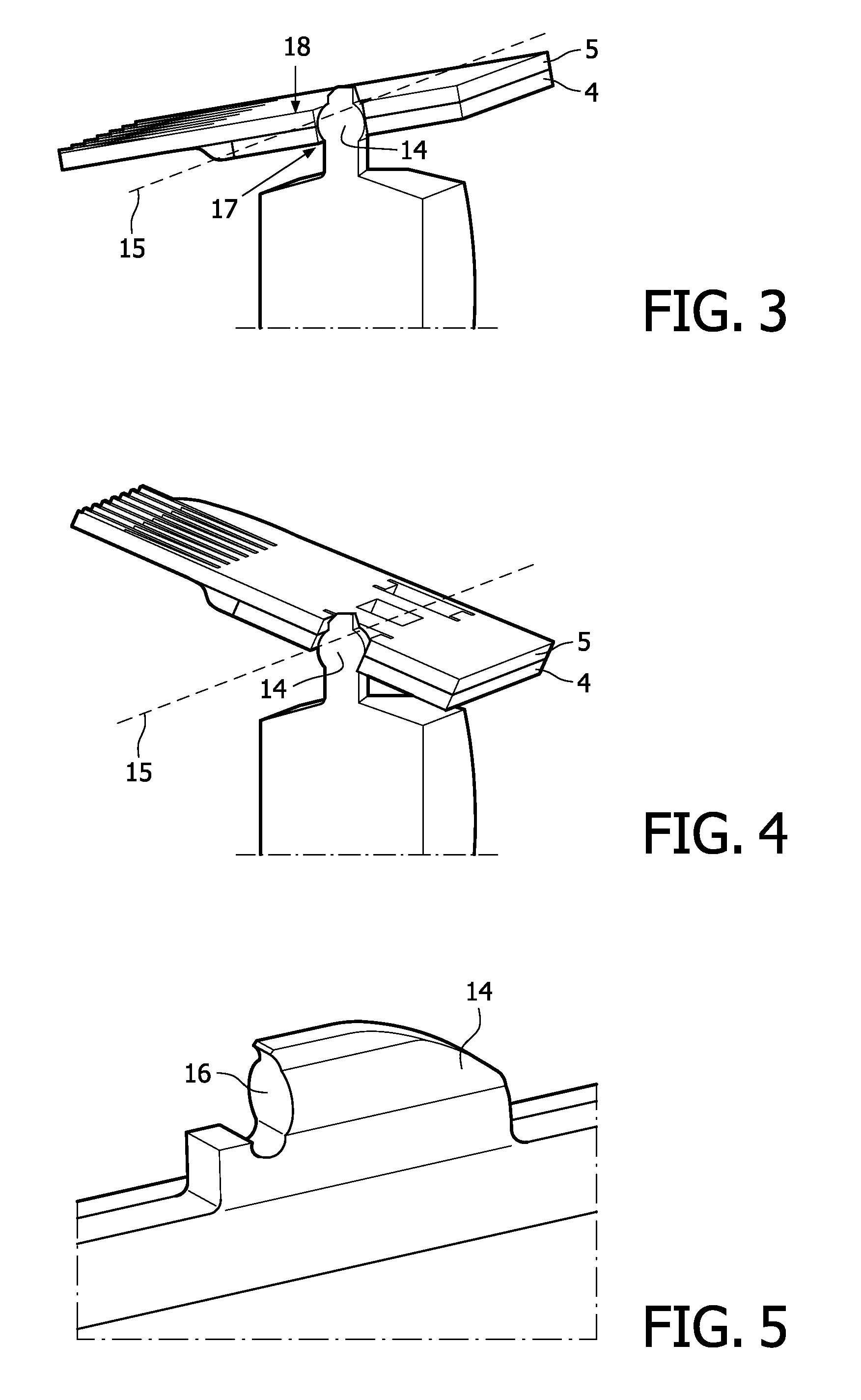
[0017]The present invention provides a solution according to which a pivotable arrangement of the cutting element is obtained without loss of stiffness in the shaving device and without a need for moving a driving source. This is realized by letting the cutting element be pivotable about an axis which is intersecting positions where the cutting element is in contact with a member of the driving means of the shaving device. In this way, the stiffness of the drive train in the shaving device may be optimal, as there is still direct contact between the driving member and the cutting element. Another important advantage is that the pivot axis is close to skin level, so that contour following may take place in a most accurate manner. In a practical embodiment, the pivot axis about which the cutting element is pivotable is extending substantially parallel to a direction in which the cutting elements are movable with respect to each other, so that the contour following may take place in a way that feels natural to a user.
[0018]Preferably, in order to prevent that a pivoting movement of the cutting element is hindered too much by friction forces, one of the contacting surfaces of the driving member and the cutting element has a convex shape, wherein another of the contacting surfaces has a shape which is deviating from a concave shape that is complementary to the convex shape of the one of the contacting surfaces. By having contacting surfaces which are shaped such that they are only capable of touching each other over a relatively small area, it is achieved that the influence of friction forces may be kept relatively small as well, wherein a pivoting movement of the cutting element with respect to the driving member may be allowed for to an extent which is sufficiently free for contour following to actually take place. At the same time, stiffness at the contacting surfaces, as seen in the direction of the reciprocating movement of the cutting element, is high, only influenced by Herzian contact deformation.

Problems solved by technology

However, this option is not at all practical, as a driving source like a motor is relatively big and heavy.
Also, if this option would be realized, the mass centre would be located so far away from an area of the shaving device which is intended for contacting skin during use of the device that the feel of the device is likely to be uncomfortable, and that the actual extent to which contour following is obtained is likely to be very limited.
At first sight, simply providing a hinge at a suitable position in the drive train may seem to be another feasible option, but this appears to be not practical either.
In fact, a force generated by the driving means would be creating high friction forces in rotation movement at the hinge.
Moreover, when such a hinge would be applied, it would not be possible to have the pivot axis close to the level of the skin without taking complex constructional measures.

Method used


Image

  • Shaving device comprising a pivotably arranged assembly of cutting elements
  • Shaving device comprising a pivotably arranged assembly of cutting elements
  • Shaving device comprising a pivotably arranged assembly of cutting elements

Examples


Embodiment Construction

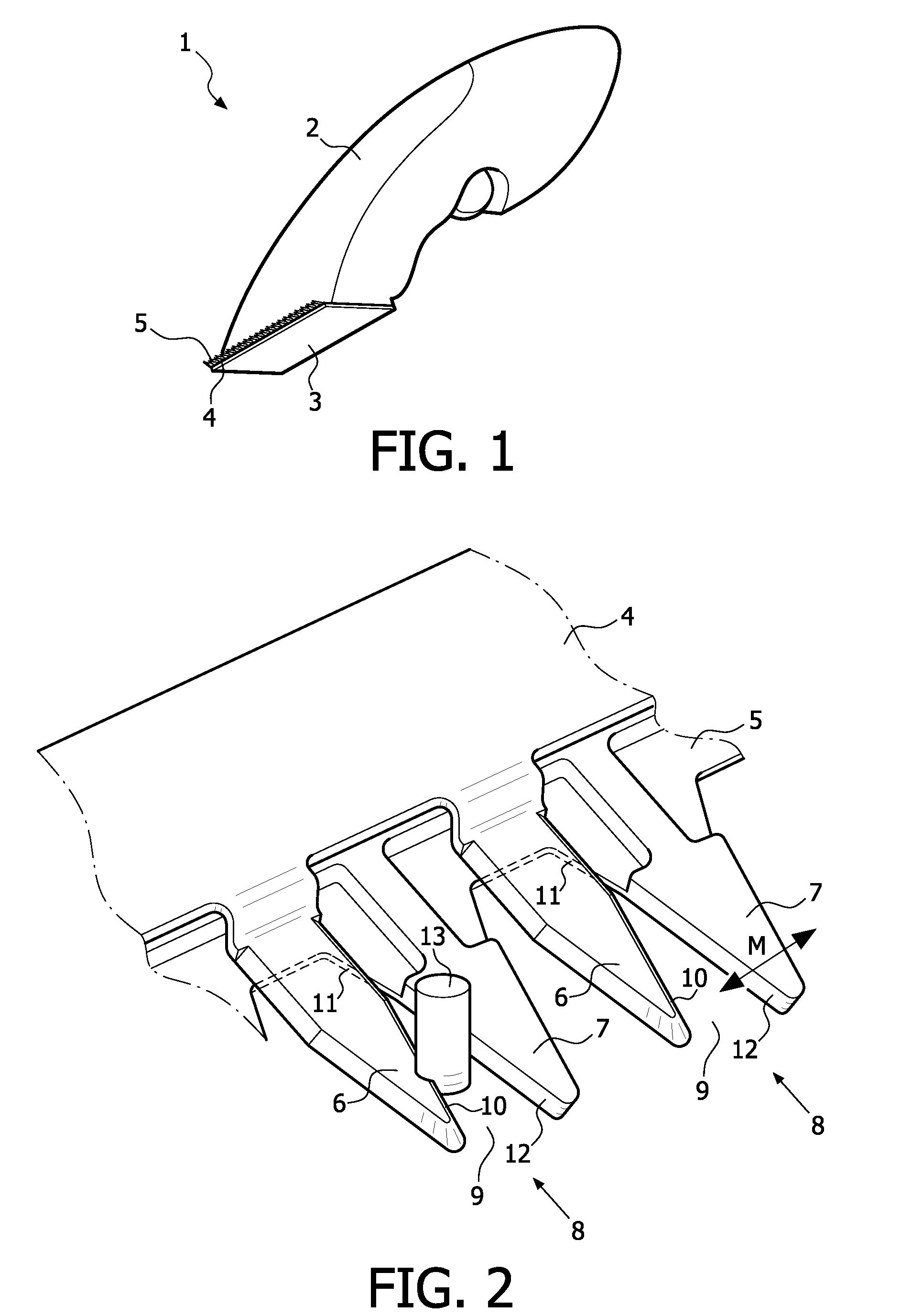
[0035]FIG. 1 shows a shaving device 1 according to the present invention, which comprises a body 2 and an assembly 3 of two elongated hair cutting elements 4, 5, wherein the said assembly 3 is mounted on the body 2.

[0036]For the purpose of performing a shaving action by means of the shaving device 1, a user of the shaving device 1 takes hold of the body 2 of the shaving device 1 and moves the assembly 3 of cutting elements 4, 5 across an area of skin where hair needs to be removed. During operation of the shaving device 1, the hair cutting elements 4, 5 are moved with respect to each other by driving means of the shaving device 1.

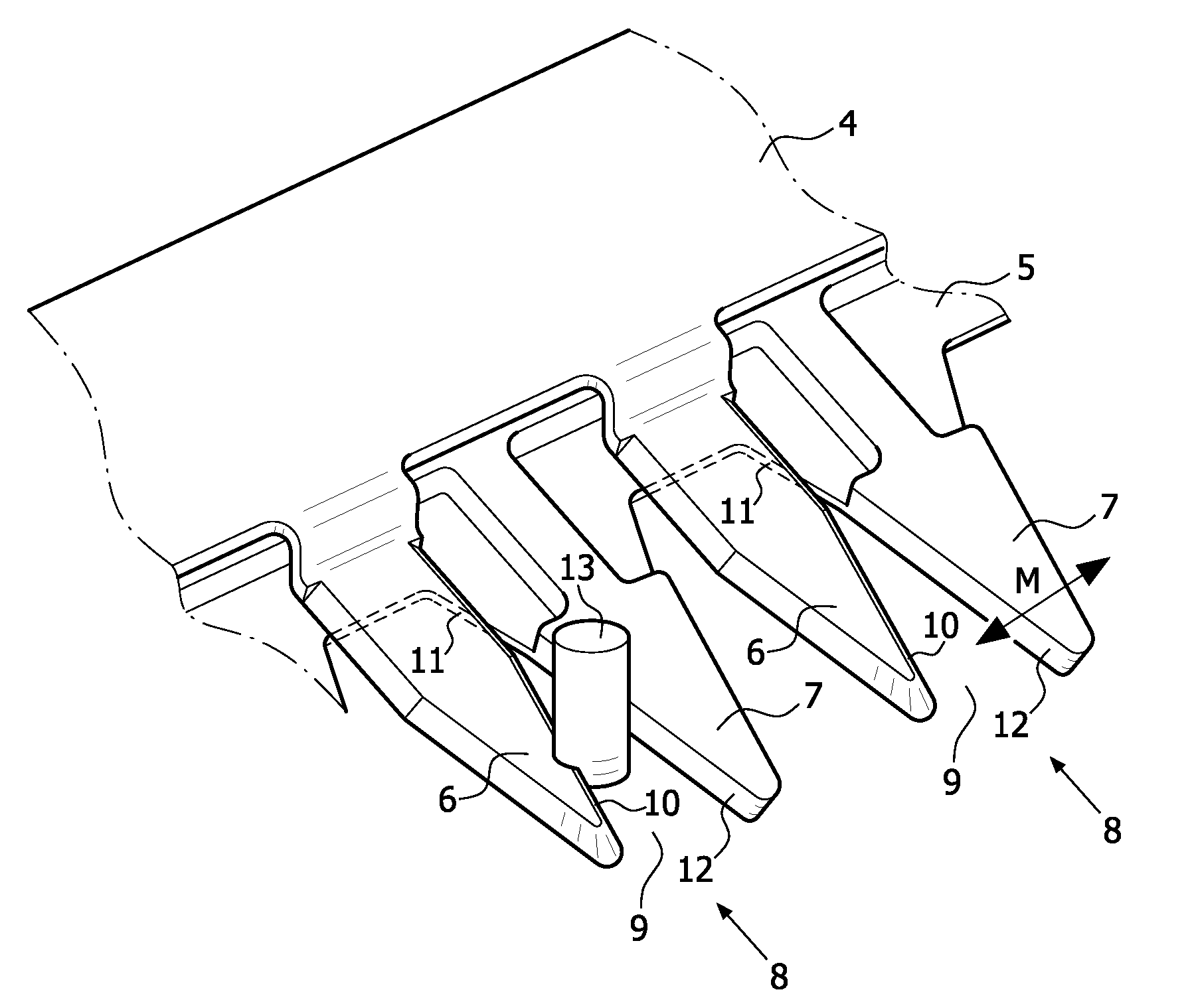
[0037]In FIG. 2, portions of the hair cutting elements 4, 5 of the shaving device 1 are shown. Both hair cutting elements 4, 5 comprise a row of substantially V-shaped teeth 6, 7. In the assembly 3 of hair cutting elements 4, 5, the hair cutting elements 4, 5 are mounted such that teeth 6, 7 of one of the hair cutting elements 4, 5 are located in spaces bet...


PUM


Abstract

A shaving device comprising cooperating hair cutting elements (4, 5) and means for driving the hair cutting elements (4, 5) is adapted to allow for automatic contour following during its application on the skin of a user. In particular, at least one cutting element (4, 5) is pivotably arranged in the shaving device, wherein a pivot axis (15) is intersecting at least one position where the cutting element (4, 5) is contacted by a driving member (14) for imposing the reciprocating movement on the cutting element (4, 5). In this way, a high drive stiffness is guaranteed, which is particularly important when a stroke of the movement of the cutting element (4, 5) is relatively small, for example, in an order of 100 μm.

Description

FIELD OF THE INVENTION[0001]The present invention relates to a shaving device, comprising an assembly of at least two cutting elements which are movably arranged with respect to each other, and which are adapted to cooperate for the purpose of cutting through hair during operation of the device; driving means for letting the hair cutting elements perform a reciprocating movement with respect to each other during operation of the device; and at least one driving member, which is part of the driving means, and which serves for imposing a reciprocating movement on at least one of the cutting elements; wherein the cutting element is pivotable about a pivot axis.[0002]The present invention also relates to a cutting element for use in a shaving device as mentioned, and to an assembly of at least two cutting elements for use in a shaving device as mentioned.BACKGROUND OF THE INVENTION[0003]A shaving device as defined in the opening paragraph is known, for example from U.S. Pat. No. 6,357,1...

Claims


Application Information

Patent Timeline
Patent Type & Authority Applications(United States)
IPC IPC(8): B26B19/06B26B19/38
CPCB26B19/063B26B19/048
Inventor VOORHORST, FOKKE ROELOFDE WIT, BASTIAAN JOHANNESBLAKE, ALASTAIR IANPRAGT, JOHAN
Owner KONINKLIJKE PHILIPS ELECTRONICS NV
Learn More