

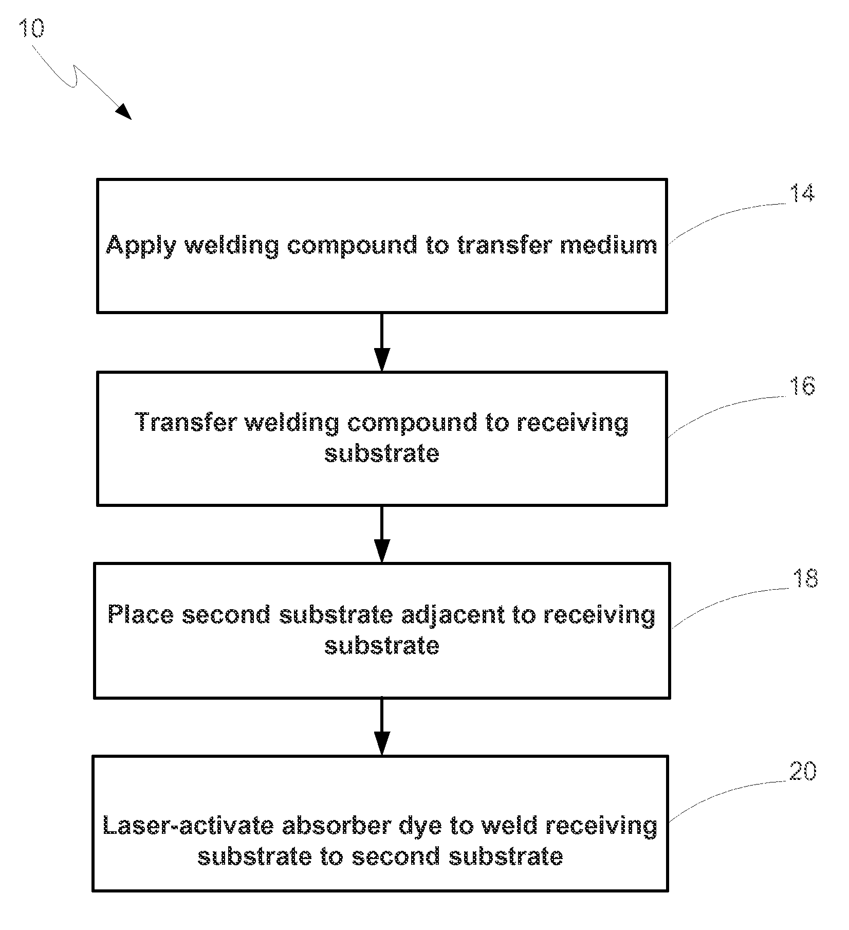
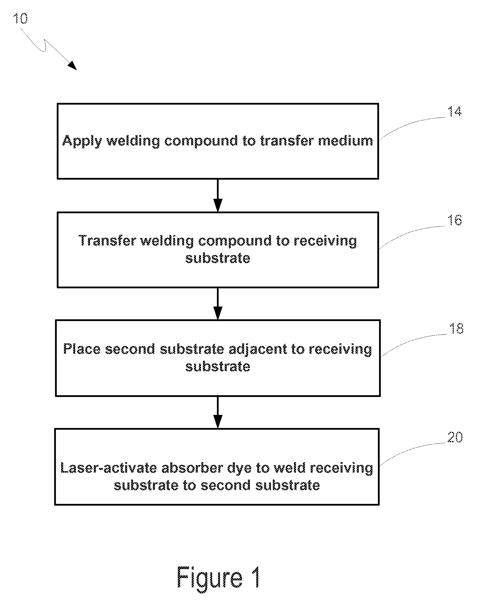
Method of laser-welding using thermal transfer deposition of a laser-absorbing dye
a laser-absorbing dye and thermal transfer technology, applied in welding/soldering/cutting articles, metal working equipment, manufacturing tools, etc., can solve the problems of inability to achieve highly precise deposition of absorber dye, thickening agents detracting from the weldability of the substrate on which the absorber dye is deposited, and many drawbacks of the use of wet absorber dye application methods
- Summary
- Abstract
- Description
- Claims
- Application Information
AI Technical Summary
Problems solved by technology
Method used
Image

Examples
example 1
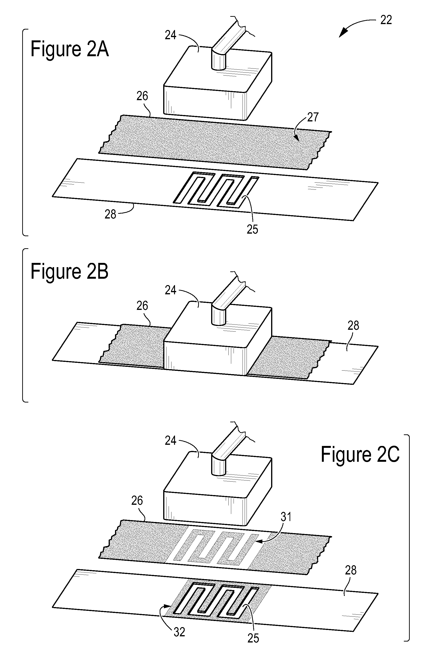
[0059]The absorber dye was applied to a transfer film consisting of 5 micron thick PET, deposited to a 1.5 mm thick polycarbonate receiving substrate, then used to weld the receiving substrate to an identical second substrate. For the deposition step, the laser source was operated at a power of 2 Watts, a speed of 50 mm / sec and a beam width of 0.7 mm (corresponding to an energy density of 0.01 J / mm2). For the welding step, the laser source was operated at a power of 40 Watts, a speed of 100 mm / sec and a beam width of 0.7 mm (corresponding to an energy density of 0.57 J / mm2).
example 2
[0060]The absorber dye was applied to a transfer film consisting of 28 micron thick aluminum foil, deposited onto a 3 mm thick acrylic receiving substrate, then used to weld the receiving substrate to an identical second substrate. For the deposition step, the laser source was operated at a power of 50 Watts, a speed of 50 mm / sec and a beam width of 4 mm (corresponding to an energy density of 0.25 J / mm2). For the welding step, the laser source was operated at a power of 100 Watts, a speed of 50 mm / sec and a beam width of 4 mm (corresponding to an energy density of 0.50 J / mm2).
[0061]Embodiments of the present invention have shown favorable results when used with several substrates, including polycarbonate (“PC”), polypropylene (“PP”), polymethyl methacrylate (“PMMA,” also commonly known as PLEXIGLAS®), low-density PE, styrene, PETG, and a blend of PE and PP. It should be understood that many other compositions may be used for the receiving substrate within the scope of this invention...
PUM
| Property | Measurement | Unit |
|---|---|---|
| thick | aaaaa | aaaaa |
| thick | aaaaa | aaaaa |
| thick | aaaaa | aaaaa |
Abstract
Description
Claims
Application Information