Supercharge Your Innovation With Domain-Expert AI Agents!

Optical apparatus with unit for correcting blur of captured image caused by displacement of optical apparatus in optical-axis direction

a technology of optical apparatus and optical apparatus, which is applied in the direction of television system, exposure control, instruments, etc., can solve the problems of not being able to accurately follow the blur, not being able to disclose nor suggest the correction of the focus blur, and the complexity of the correction system, so as to reduce the blurring effect of focus and accurately following the blur

Inactive Publication Date: 2010-12-02
CANON KK
View PDF5 Cites 0 Cited by
  • Summary
  • Abstract
  • Description
  • Claims
  • Application Information

AI Technical Summary

Benefits of technology

The present invention provides an optical apparatus that can capture images without focus blurring caused by hand-induced shake. The apparatus includes a lens system with a focus lens and an image pickup element that converts the image into an image signal. The apparatus also includes an auto-focus unit that moves the focus lens to bring the image into an in-focus state, a displacement detection unit that detects the displacement of the apparatus in the direction of the optical axis, and a focus-range setting unit that calculates an acceptable range of detected displacement within which it is assumed that the image remains in an in-focus state. The control unit is operable to capture one or more images in a given time period from the pickup element when the detected displacement is within the acceptable range. This invention allows for more focused images to be obtained even if a blur in the optical-axis direction affects the image captured.

Problems solved by technology

First, as the focus lens is moved in the optical-axis direction, the angle of field is changed. This is one of the important factors of the deterioration in images when high magnification image-capture such as macro image-capture is performed. If a lens for correcting the angle of field is additionally provided for preventing the deterioration in images, the correction system may become complicated. Further, an existing focus lens driving system for auto-focusing cannot accurately follow the blur because the driving characteristic of a motor is insufficient and the backlash is large. While the technique of Japanese Patent No. 03110797 is effective for a shift blur, the patent does not disclose nor suggest correction of a focus blur.

Method used


Image

  • Optical apparatus with unit for correcting blur of captured image caused by displacement of optical apparatus in optical-axis direction
  • Optical apparatus with unit for correcting blur of captured image caused by displacement of optical apparatus in optical-axis direction
  • Optical apparatus with unit for correcting blur of captured image caused by displacement of optical apparatus in optical-axis direction

Examples


first embodiment

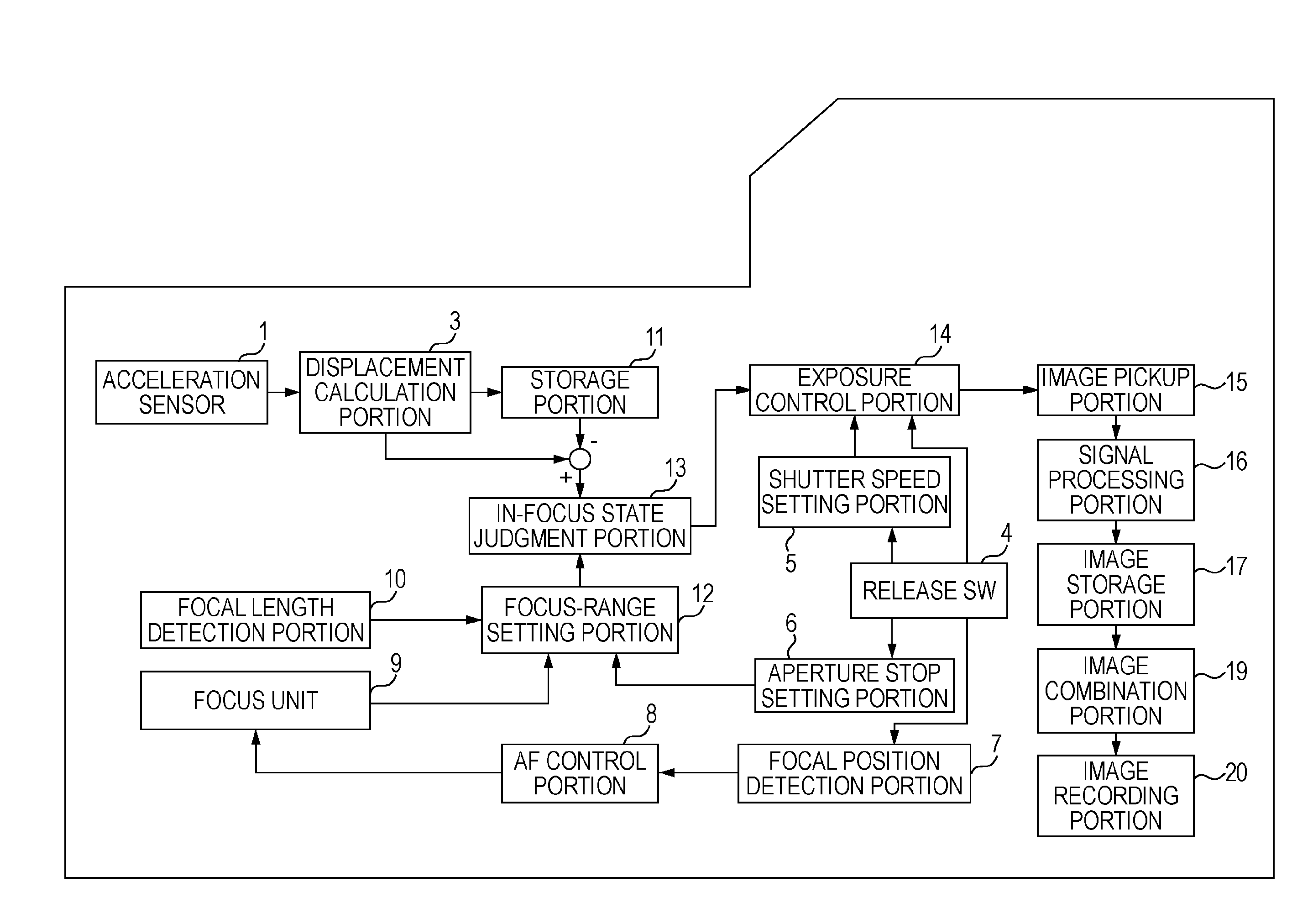
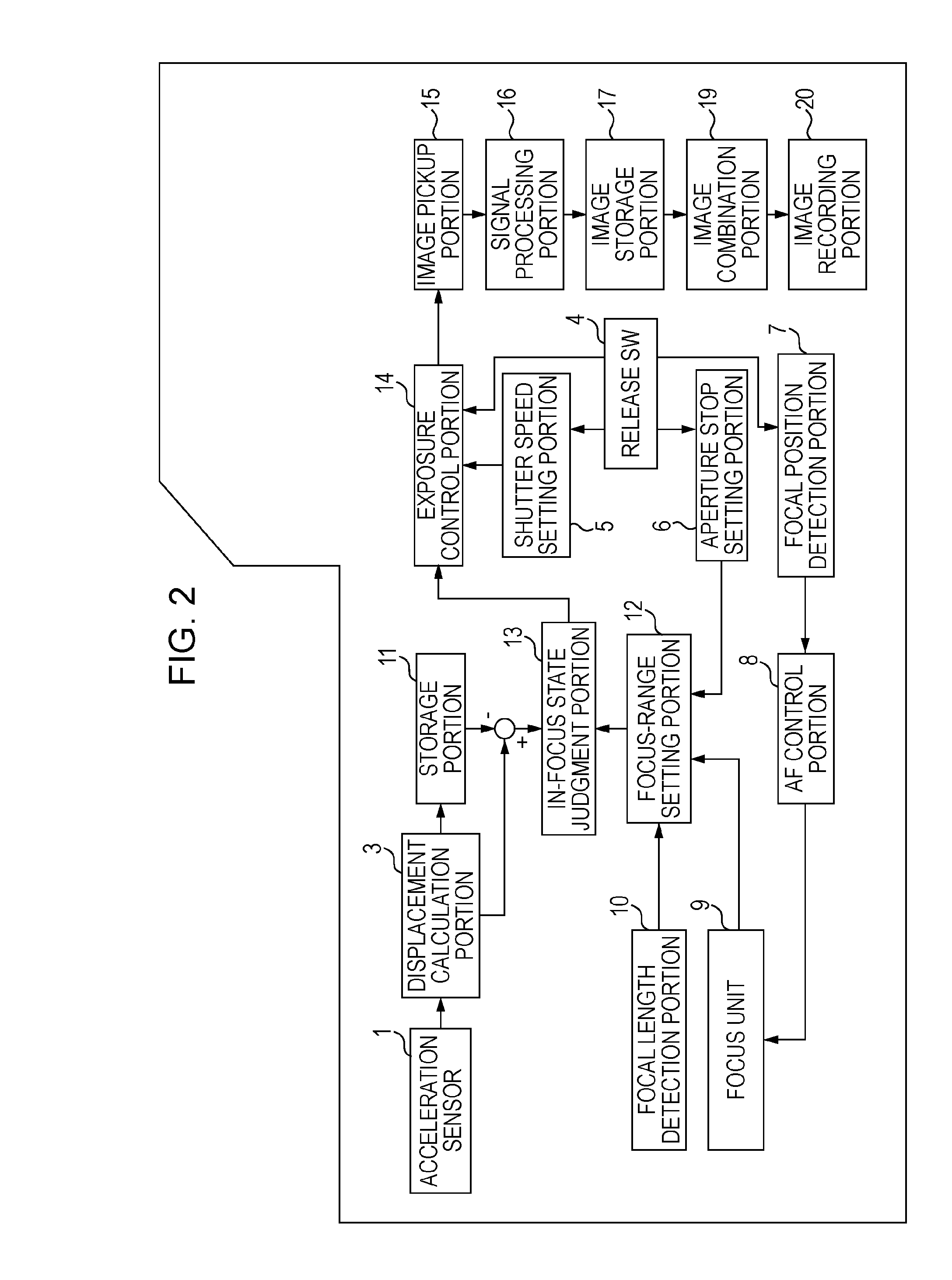
[0035]FIG. 2 is a block diagram showing the function of a digital single-lens reflex camera with an interchangeable lens. The camera is an optical apparatus according to a first embodiment of the present invention.

[0036]An acceleration sensor 1 detects the acceleration of the camera in an optical-axis direction. A displacement calculation portion 3 calculates the displacement of the blur in the optical-axis direction by applying second-order integration to a signal obtained such that an output of the acceleration sensor 1 is subtracted by a direct-current (DC) component (i.e., electrical DC offset and DC component caused by acceleration due to gravity).

[0037]A release switch 4 can be half pressed (SW1) or fully pressed (SW2). A shutter speed setting portion 5 sets the shutter speed when the release switch 4 is half pressed (SW1). An aperture stop setting portion 6 sets the aperture value.

[0038]A focal position detection portion 7 detects a focused position of an object. An autofocus...

second embodiment

[0078]In the above-described first embodiment, the acceleration sensor is used for detection of a focus blur. Also, a blur correction function is arranged for correcting a blur in the direction orthogonal to the optical axis.

[0079]In a second embodiment, an acceleration sensor and an angular speed sensor are used for detection of a focus blur. Also, a motion blur optical correction unit and a motion blur electronic correction unit are arranged for correcting a blur in the direction orthogonal to the optical axis.

[0080]The second embodiment is described with reference to FIGS. 10 to 13. Like numerals refer like components as in the first embodiment. Also, descriptions of operations similar to those of the first embodiment are omitted. Operations unique to the second embodiment are mainly described.

[0081]FIG. 10 is a block diagram showing the function of a digital single-lens reflex camera with an interchangeable lens, the camera which is an optical apparatus according to the second e...


PUM


Abstract

A focus range is determined on the basis of an object distance, focal distance, and aperture value, after an autofocus operation. When SW2 is operated, an exposure is performed only during a period that a displacement of a blur in an optical-axis direction is within the focus range. If an exposure time for one exposure does not reach an exposure time to obtain an optimum exposure, a plurality of exposures are performed until a total exposure time reaches the exposure time to obtain the optimum exposure. When the plurality of exposures are performed, a plurality of images obtained are combined to generate an image with the optimum exposure.

Description

[0001]The present application is a divisional of U.S. patent application Ser. No. 11 / 957,263, filed Dec. 14, 2007, entitled “OPTICAL APPARATUS WITH UNIT FOR CORRECTING BLUR OF CAPTURED IMAGE CAUSED BY DISPLACEMENT OF OPTICAL APPARATUS IN OPTICAL-AXIS DIRECTION”, the content of which is expressly incorporated by reference herein in its entirety. Further, the present application claims priority from Japanese Patent Application No. 2006-343430, filed Dec. 20, 2006, which is also hereby incorporated by reference herein in its entirety.BACKGROUND OF THE INVENTION[0002]1. Field of the Invention[0003]The present invention relates to a technique of improving deterioration of a captured image caused by hand shake during image captured by an optical apparatus such as a digital camera. In particular, the present invention relates to a technique of reducing image blurring caused, for example, by hand movement in the optical-axis direction during macro image-capturing.[0004]2. Description of the...

Claims


Application Information

Patent Timeline
Patent Type & Authority Applications(United States)
IPC IPC(8): H04N5/228H04N23/40H04N25/00
CPCG02B7/28G03B17/00G03B2217/005H04N5/23248H04N5/23258H04N5/23267H04N5/2327H04N5/23287H04N5/243H04N19/51H04N23/684H04N23/683H04N23/68H04N23/6812H04N23/687H04N23/76
Inventor OKADA, KOUJI
Owner CANON KK
Features
  • R&D
  • Intellectual Property
  • Life Sciences
  • Materials
  • Tech Scout
  • Unparalleled Data Quality
  • Higher Quality Content
  • 60% Fewer Hallucinations
Learn More