Variant packaging structure for a solar module

Inactive Publication Date: 2010-12-09
CHIP CITY SCI & TECH
View PDF4 Cites 12 Cited by
  • Summary
  • Abstract
  • Description
  • Claims
  • Application Information

AI Technical Summary

Benefits of technology

[0007]Apart from being able to convert solar energy into electric energy, the solar module of this invention can be made into various shapes for increasing decorative effect.

Problems solved by technology

In spite of being able to convert solar energy into electric energy, the conventional solar panel 1 is quite monotonous and unvarying in an external appearance and hence it is usually installed on the roof of a building or at a location where people can hardly see it in order to avoid spoiling the external beauty of the building.

Method used


Image

  • Variant packaging structure for a solar module
  • Variant packaging structure for a solar module
  • Variant packaging structure for a solar module

Examples


Embodiment Construction

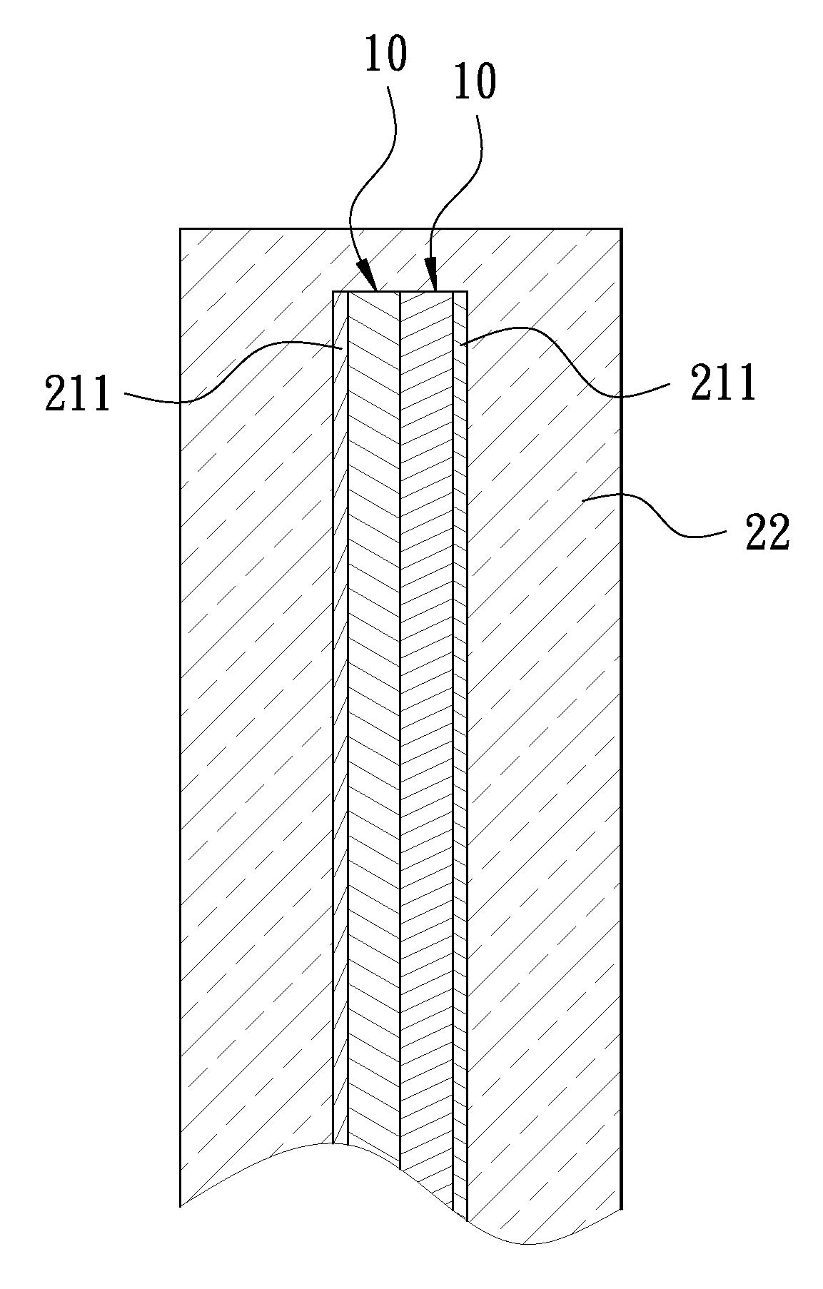
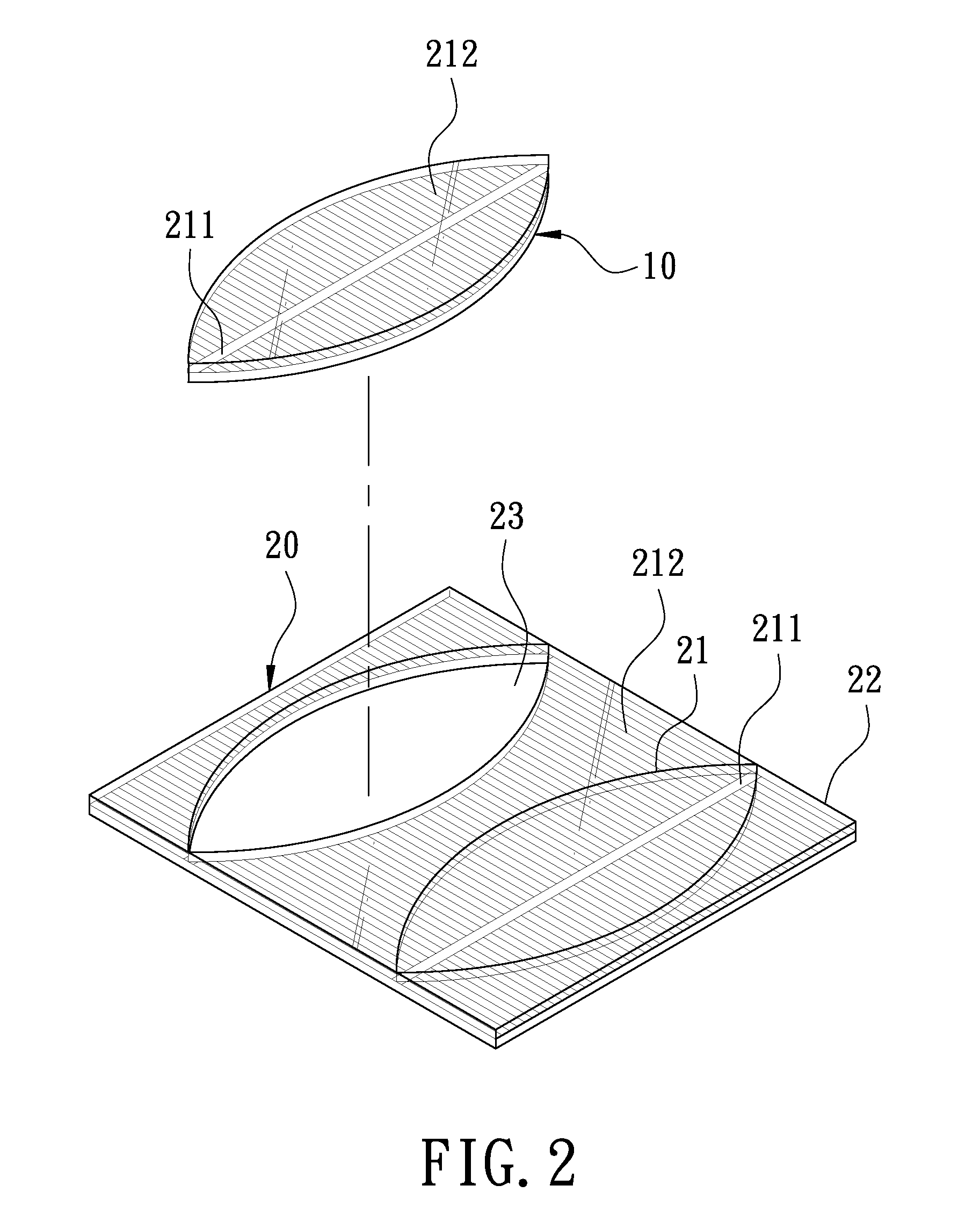
[0014]A first preferred embodiment of a variant packaging structure for a solar module in the present invention, as shown in FIG. 2, includes a solar module 10 shaped as an oval leaf and formed with a portion cut off a solar panel 20. The solar panel 20 has one side surface provided with a plurality of welded wires 21 respectively composed of plural main welded wires 211 and lots of connection welded wires 212. The main welded wires 211 spaced apart in parallel are disposed on the surface of the solar panel 20, while the connection welded wires 212 are formed at the opposite sides of the main welded wires 211, spaced apart and perpendicular to the main welded wires 211. Further, the solar panel 20 has an outer side sealed with a packaging layer 22 made of transparent epoxy resin. After being cut to make up the solar module 10 with the main welded wire 211 serving as a center line, the solar panel 20 will have a through hole 23 with a same shape as the solar module 10.

[0015]A second ...


PUM


Abstract

A variant packaging structure for a solar module in the present invention includes a solar module that is shaped as a non-regular square and has an outer side sealed with a packaging layer. In addition to having function of converting solar energy into electric energy, the solar module of this invention can be made into various shapes for increasing decorative effect.

Description

BACKGROUND OF THE INVENTION[0001]1. Field of the Invention[0002]This invention relates to a variant packaging structure for a solar module.[0003]2. Description of the Prior Art[0004]Generally, a conventional solar panel 1 is square-shaped in an external appearance and has one side surface provided with two main welded wires 2 and lots of connection welded wires 3, as shown in FIG. 1. The main welded wires 2 are disposed on the surface of the solar panel 1, spaced apart and arranged in parallel, while the connection welded wires 3 are disposed at the opposite sides of the main welded wires 2, spaced apart and perpendicular to the main welded wires 2.[0005]In spite of being able to convert solar energy into electric energy, the conventional solar panel 1 is quite monotonous and unvarying in an external appearance and hence it is usually installed on the roof of a building or at a location where people can hardly see it in order to avoid spoiling the external beauty of the building. Th...

Claims


Application Information

Patent Timeline
IPC IPC(8): H01L31/048
CPCH01L31/022433H01L31/035281Y02E10/46Y02E10/50H01L31/048
Inventor HUANG, MIN-HSUN
Owner CHIP CITY SCI & TECH
Why Eureka
Try Eureka