
Telescopic prop-up pole device

a prop-up pole and telescopic technology, applied in the direction of mechanical equipment, other domestic objects, machine supports, etc., can solve the problems of difficult practical use, complex fix operation and loosen operation, and difficult to use, and achieve excellent durability and excellent durability.

Inactive Publication Date: 2010-12-09
DREAMWARE
View PDF16 Cites 14 Cited by
  • Summary
  • Abstract
  • Description
  • Claims
  • Application Information

AI Technical Summary

Benefits of technology

The present invention provides a telescopic prop-up pole device that is simple to adjust and durable. The device includes a first pole, a second pole, and a telescoping adjustment body. The telescoping adjustment body has an upper cylindrical body and a lower cylindrical body that are hollow and cylindrical. The upper cylindrical body has a lever loading part and a lever supporting part, while the lower cylindrical body has a pole pressure-contacting / releasing part. The device also includes an operation lever that pushes up the pressure-contacting annular body to bring it into the horizontal state to eliminate bulging and into the inclined state to cause one side to bulge, thereby releasing the pole pressure-contacting / releasing part. The technical effect of the invention is to provide a telescopic prop-up pole device that is easy to adjust and durable.

Problems solved by technology

As such a telescopic pole device, that with which the telescoping adjustment body is of turnbuckle structure, and with a turning operation thereof, the upper pole is fixed or loosened has been conventionally known, however, with such a telescoping adjustment body of turnbuckle structure, the screw tightening structure makes the fixing operation and loosening operation complex, and in addition, there can arise a problem on durability that, with a number of times of operation, the function of the turnbuckle structure is impaired, resulting in occurrence of difficulty for practical use.
With this telescopic pole device, the operation of tightening the stopper screw and that of loosening thereof are complex, and there can arise a problem on durability that, with a number of times of operation, the function of the screw structure is impaired, resulting in occurrence of difficulty for practical use.

Method used


Image

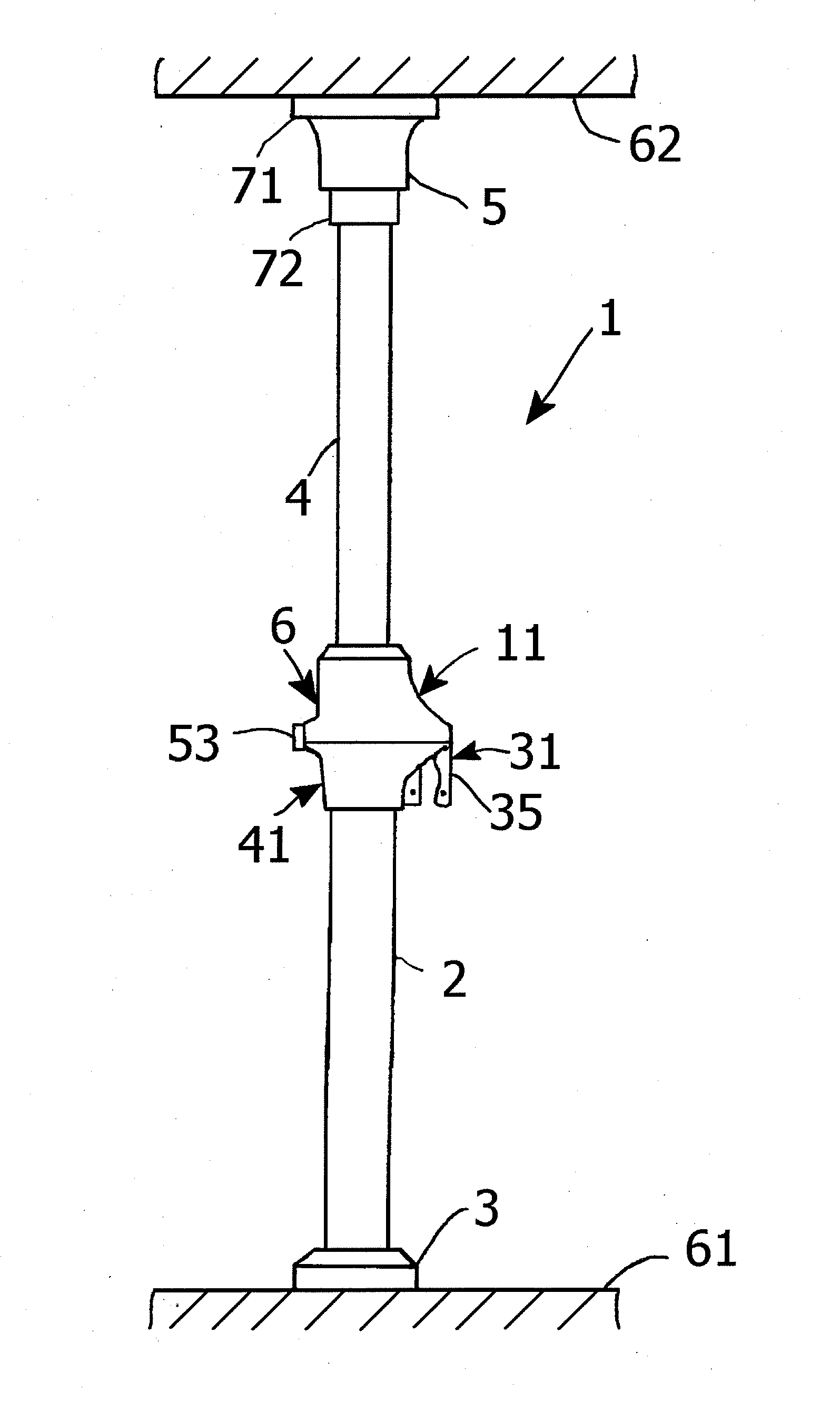
  • Telescopic prop-up pole device
  • Telescopic prop-up pole device
  • Telescopic prop-up pole device

Examples


embodiment 1

[0026]Hereinbelow, a telescopic prop-up pole device 1 according to an embodiment 1 of the present invention will be described.

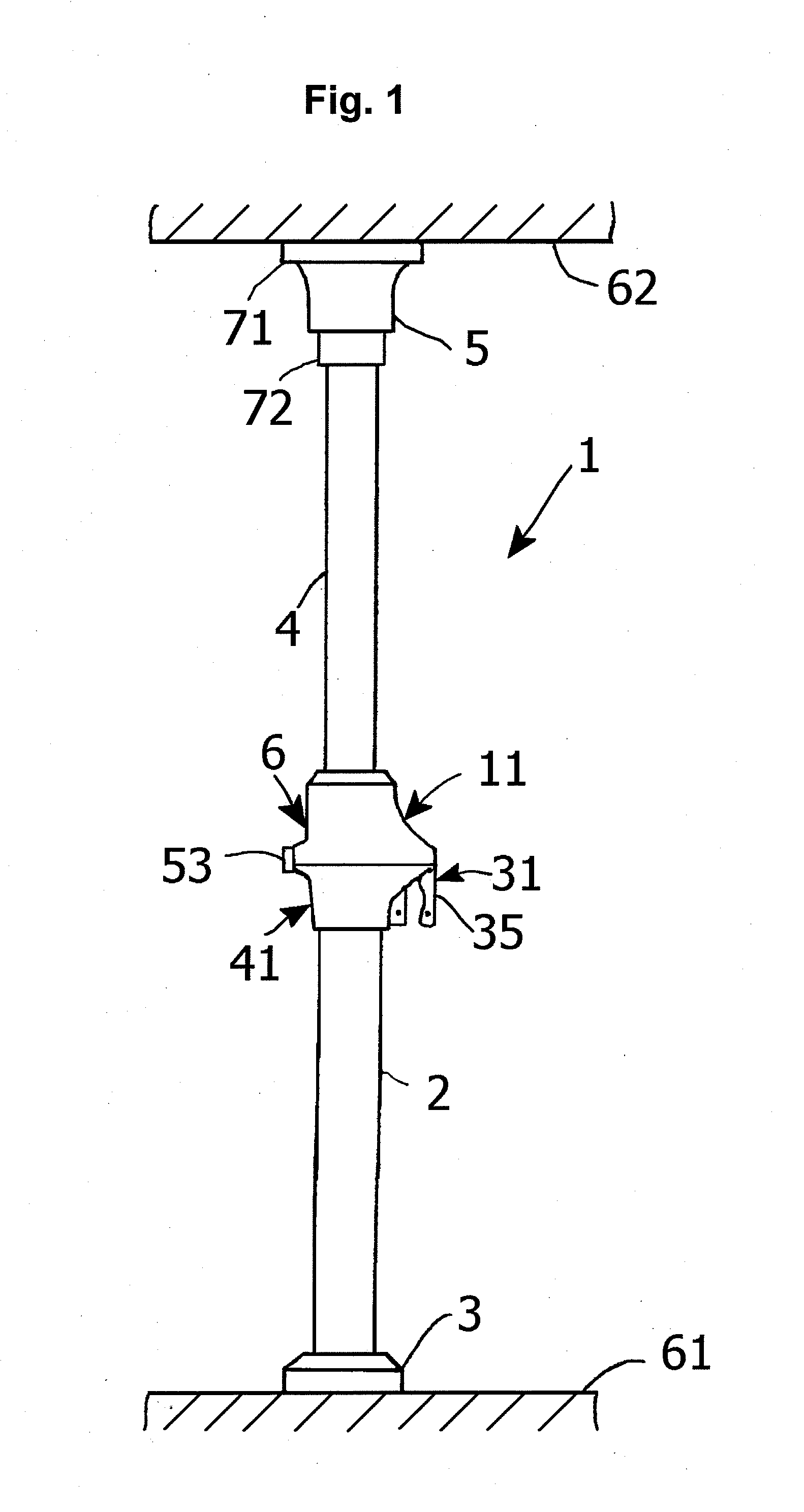
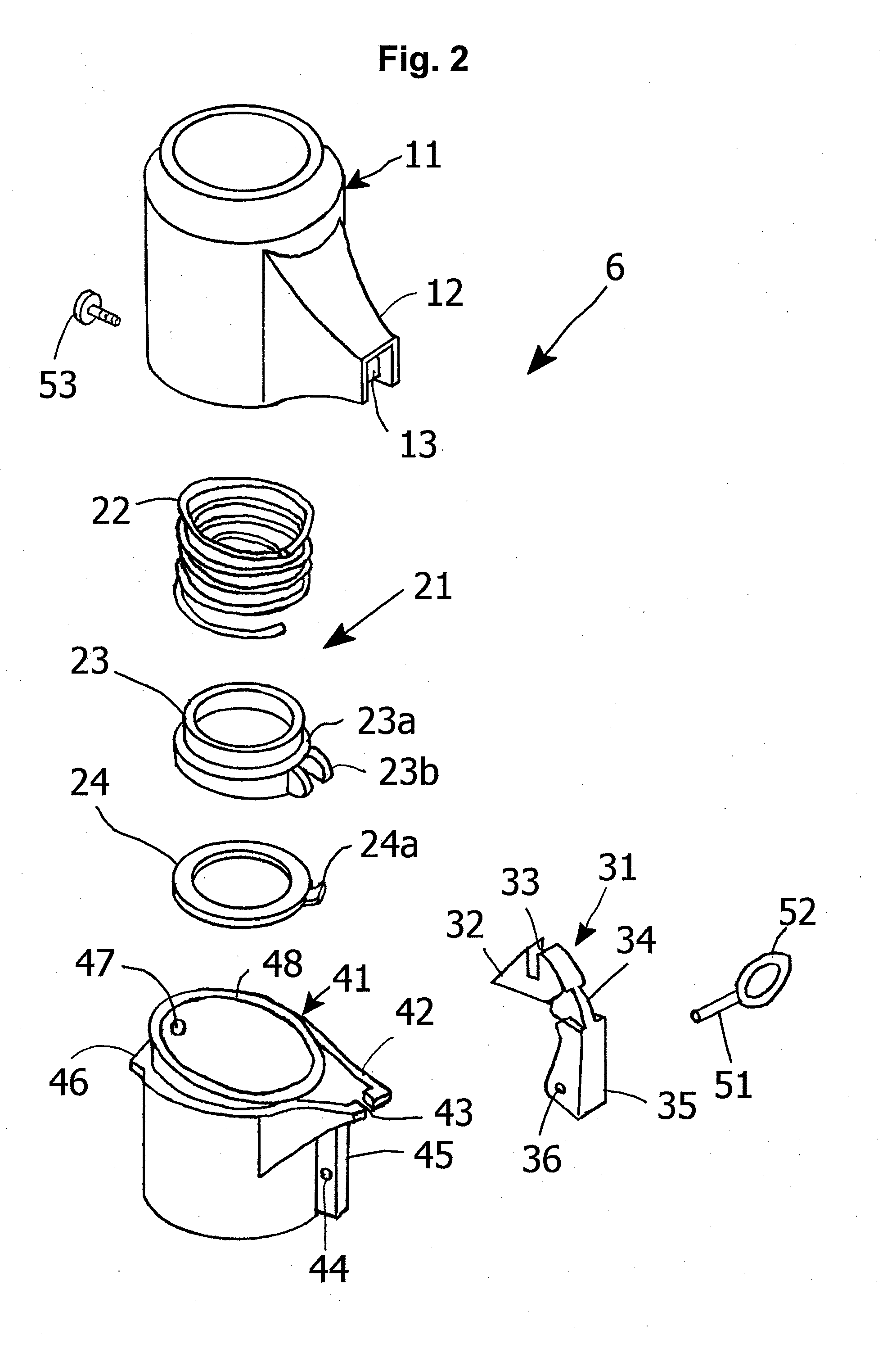
[0027]As shown in FIG. 1, the telescopic prop-up pole device 1 of the present embodiment 1 comprises a cylindrical or round-bar shaped first pole 2 made of, for example, synthetic resin or metal that is vertically erected on a floor 61, for example; a cylindrical or round-bar shaped second pole 4 a part of which is drawably inserted in the lengthwise direction into the inside of this first pole 2, being protruded, and which is cylindrically formed, being made of, for example, synthetic resin or metal, and having an outside diameter slightly smaller than the inside diameter of the first pole 2; a telescoping adjustment body 6 for telescoping adjustment of this second pole 4 which is disposed over one end of the first pole 2 and a part of second pole 4 extending outward from this one end; a first butting body 3 to which the lower end of the first pole 2 is remo...

embodiment 2

[0063]Next, a telescopic prop-up pole device 1A according to an embodiment 2 of the present invention will be described with reference to FIG. 6 to FIG. 9.

[0064]For the telescopic prop-up pole device 1A of the present embodiment 2, the same elements as those of the telescopic prop-up pole device 1 of the embodiment 1 as described above will be provided with the same reference numerals or letters, with the detailed explanation thereof being omitted.

[0065]As shown in FIG. 6 and FIG. 7, the basic configuration of the telescopic prop-up pole device 1A of the present embodiment 2 is substantially the same as that of the telescopic prop-up pole device 1 of the embodiment 1. Specifically, the telescopic prop-up pole device 1A of the present embodiment 2 is characterized in that, instead of the aforementioned operation lever 31 of turning operation type, an operation lever 81 of pushbutton type has been adopted, and the geometries of the lever loading part 12 of the upper cylindrical body 1...

embodiment 3

[0080]Next, a telescopic prop-up pole device 1B according to an embodiment 3 of the present invention will be described with reference to FIG. 10.

[0081]The telescopic prop-up pole device 1B according to the present embodiment 3 is characterized in that it utilizes the telescopic prop-up pole device 1 of the embodiment 1, and further to the second pole 4 (or the first pole 2), a desired number (two in an example as shown in FIG. 10) of hooks 91 for hanging clothes such as a shirt, a towel, a hat, and the like, are fitted in a desired location thereof. The other configuration of the telescopic prop-up pole device 1B is the same as that of the embodiment 1.

[0082]According to the telescopic prop-up pole device 1B of the present embodiment 3, as is the case with the aforedescribed embodiments, there can be realized and provided a telescopic prop-up pole device 1B with which the operability is good; yet the durability is excellent because, unlike the conventional telescopic prop-up pole d...


PUM


Abstract

A telescopic prop-up pole device of the present invention is configured to comprise a first pole; a second pole which is drawably inserted into this first pole, while being protruded; and a telescoping adjustment body for adjusting the protruding length of the second pole, the telescoping adjustment body being constituted by an upper cylindrical body; a lower cylindrical body; a pole pressure-contacting / releasing part including a pressure-contacting annular body having a protrusion and a coil spring; and an operation lever which, with a turning operation thereof, pushes up this pole pressure-contacting / releasing part, and the turning operation of the operation lever pushes up the protrusion on one side of the pressure-contacting annular body against the resilience of the coil spring for bringing the pressure-contacting annular body into the horizontal state to eliminate the bulging of one side and the other side thereof toward the circumference side of the second pole and thereby to bring the pole pressure-contacting / releasing part into the second pole releasing state, while, with the turning operation thereof being canceled, the pressure-contacting annular body is brought into an inclined state under the resilience of the coil spring with one side and the other side thereof being bulged toward the circumference side of the second pole and thereby the pole pressure-contacting / releasing part being brought into the second pole pressure-contacted state.

Description

TECHNICAL FIELD[0001]The present invention relates to a telescopic prop-up pole device which is simple in telescoping adjustment of a length-adjusting pole and also excellent in durability.BACKGROUND ART[0002]With the telescopic pole device constituting the main part of a pole type hanger which is used for hanging clothes and the like, being installed between the floor and ceiling in an interior or other narrow space, a telescoping adjustment body is jointed and fixed to the upper end part of a lower pole with a larger bore that is to be erected from the floor, for example; an upper pole with a bore smaller than that of the lower pole is drawably inserted inward from the upper end side of the lower pole while being passed through the telescoping adjustment body; and by means of the telescoping adjustment body, the upper pole is fixed or loosened, whereby the upper pole is fixed and jointed to the lower pole or made telescopable with respect to the lower pole.[0003]As such a telescop...

Claims


Application Information

Patent Timeline
Patent Type & Authority Applications(United States)
IPC IPC(8): E04G25/04E04G25/08D06F53/04
CPCD06F53/04
Inventor LEE, CHEOL JOONG
Owner DREAMWARE
Learn More