Sensor system and reverse clamping mechanism

a technology of a sensor system and a clamping mechanism, which is applied in the direction of mechanical measuring arrangements, instruments, manufacturing tools, etc., can solve the problems of incongruous tightening of the fasteners for each sensor or person, and introduce inherent inaccuracy between sensors

Inactive Publication Date: 2010-12-09
PERCEPTRON
View PDF14 Cites 17 Cited by
  • Summary
  • Abstract
  • Description
  • Claims
  • Application Information

AI Technical Summary

Benefits of technology

[0007]In satisfying the above need, as well as overcoming the enumerated drawbacks and other limitations of the related art, the present application provides a se

Problems solved by technology

As such, the tightening of the fasteners may not be consistent for each sensor or person.
Inherent inaccuracies can be i

Method used


Image

  • Sensor system and reverse clamping mechanism
  • Sensor system and reverse clamping mechanism
  • Sensor system and reverse clamping mechanism

Examples


Embodiment Construction

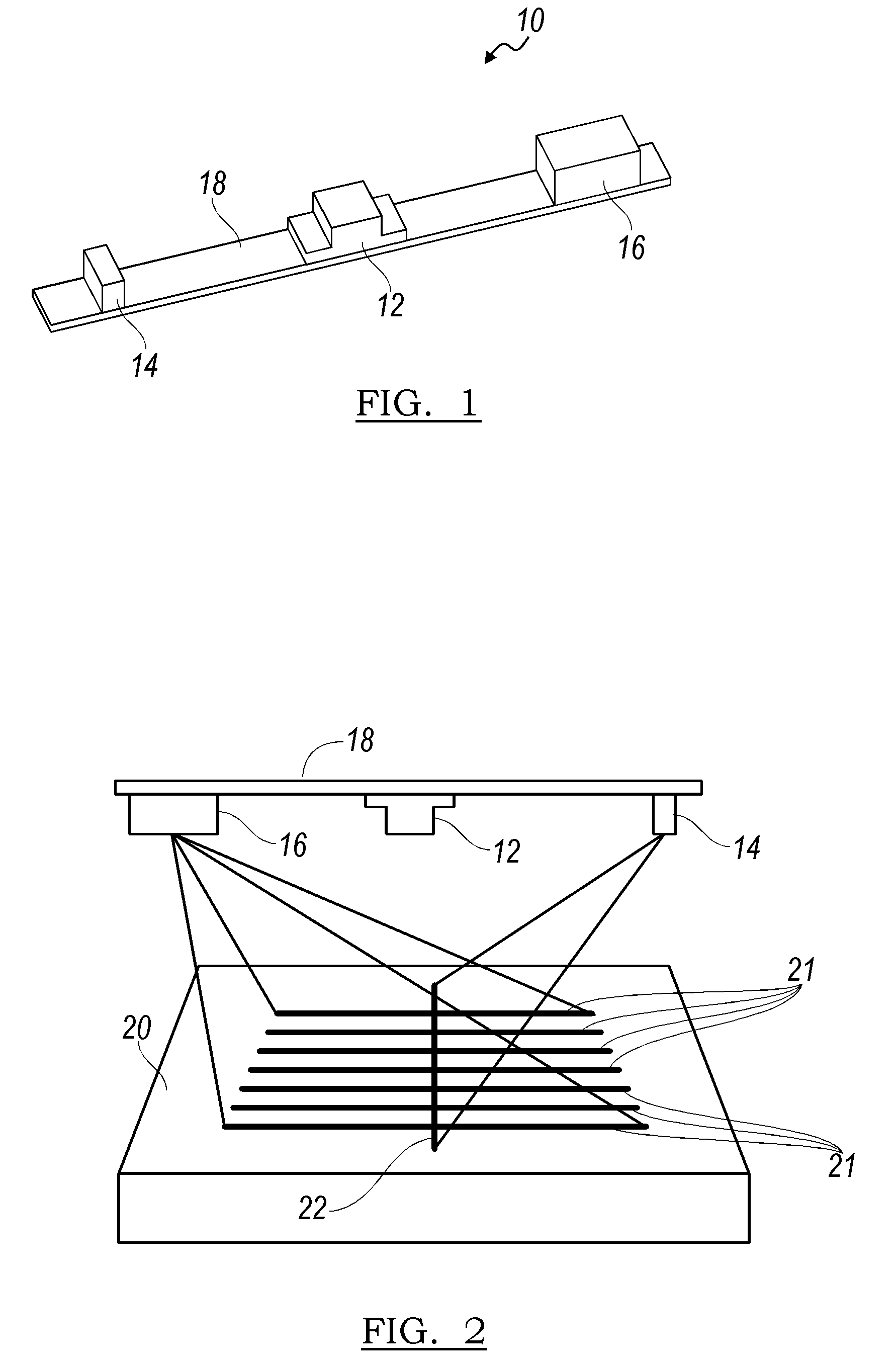
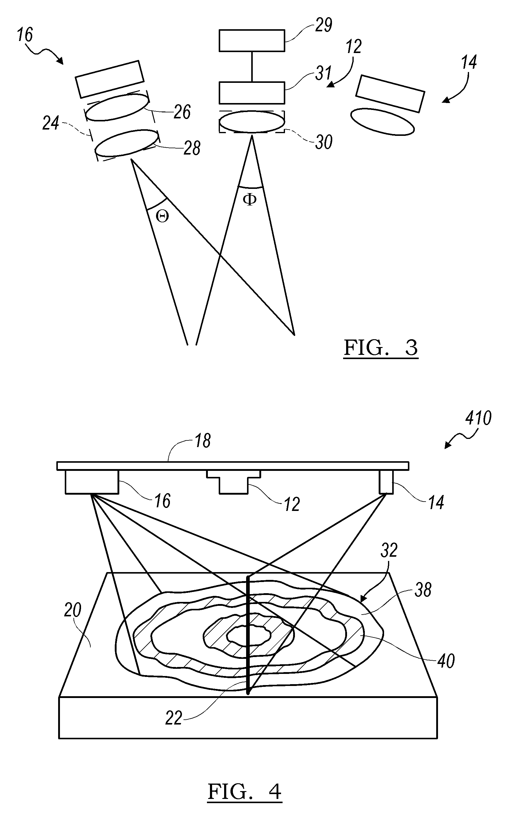
[0034]Referring now to FIG. 1, a system embodying the principles of the present application is illustrated therein and designated at 10. The system 10 includes sensor 12, a first laser source 14, a second laser source 16, and a mounting structure 18.

[0035]The sensor 12 may comprise a camera including receiving optics and a detector such as a CCD or CMOS array. Accordingly, the sensor 12 has a field of view that projects outwardly from the camera and a range of focus that is defined by the receiving optics of the sensor. The field of view and depth of focus define a sensing volume of the sensor 12. The first laser source 14 may project one or more laser lines onto an object. If more than one laser line is projected from the first laser source 14 the lines may be parallel to one another. In addition, the laser lines may be equally spaced with respect to each other. The first laser source 14 is oriented at an angle relative to the sensor such the laser lines intersect the field of view...


PUM

PropertyMeasurementUnit
Angleaaaaaaaaaa
Diameteraaaaaaaaaa
Radiusaaaaaaaaaa

Abstract

A sensor system and a reverse clamp is provided. The reverse clamp may include a back portion, a first arm, and a second arm. The first and second arm extending from the back portion to form an opening configured to receive a cylindrical arm.

Description

PRIORITY CLAIM[0001]This application is a continuation-in-part of U.S. application Ser. No. 12 / 474,911 filed on May 29, 2009, which is incorporated in its entirety by reference herein.BACKGROUND[0002]1. Field of the Invention[0003]The present application is generally related to sensor system and a reverse clamp.[0004]2. Description of Related Art[0005]Optical sensing systems require precise calibration and alignment. However, many sensors utilize fasteners to mount components such as sensors or illumination sources into a sensor structure. As such, the tightening of the fasteners may not be consistent for each sensor or person. Inherent inaccuracies can be introduced between sensors even during the alignment and calibration processes due to torque variation in the fasteners.[0006]In view of the above, it is apparent that there exists a need for an improved sensor system.SUMMARY[0007]In satisfying the above need, as well as overcoming the enumerated drawbacks and other limitations of...

Claims


Application Information

Patent Timeline
IPC IPC(8): G01B11/24G06G7/64F16B2/02B23P17/00
CPCB25B5/06B25B5/147G01B5/0004G01B11/25G01B11/2531Y10T29/49G01B11/2755G01B2210/286G01B2210/52G06T7/0057Y10T24/44G01B11/2545G06T7/521
Inventor CROWTHER, DAVID
Owner PERCEPTRON
Why Eureka
Try Eureka