
Image reading apparatus

Inactive Publication Date: 2010-12-09
CANON KK
View PDF4 Cites 14 Cited by
  • Summary
  • Abstract
  • Description
  • Claims
  • Application Information

AI Technical Summary

Benefits of technology

[0008]The present invention has been conceived in light of the above conventional examples, and provides an image reading apparatus, particularly an image reading apparatus that adopts a configuration in which the sheet-through method with the use of a white plate is adopted, that discerns and detects black dust and white dust on a platen glass, and dust on a white plate, and can correct noise due to various types of detected dust, and a method for correcting image data.
[0012]According to the invention in this application, it is possible to discern and detect black dust and white dust on the platen glass, and dust on the white plate. Accordingly, processing for correcting noise due to each type of dust is performed, which contributes to the improvement in image quality.

Problems solved by technology

In view of this, a configuration in which a white plate is used is desirable in terms of cost; however, there are some problems with regard to countermeasures if a white plate is used.
A first problem is that soiling of a white plate appears as noise of image data, and it is difficult to remove this noise.
However, with the invention disclosed in Japanese patent No. 3337993 in which a white sheet is used as the rear side, it is not possible to distinguish between dust on the platen glass and dust on the white plate.
However, if a white plate is used, soiling such as dust on the white plate is read as is, and thus it appears as obvious noise.
Further, a second problem is that if the darkness of soiling such as dust is low, and the soiling is close to white, the difference of a reading darkness level relative to the belt or the roller on the back is small, and thus such soiling is difficult to be distinguished.
Further, since it is difficult to distinguish whether white dust is dust adhering to the platen glass or dust adhering to the white roller or white plate, there is also a problem that it is difficult to select correction processing for reducing or eliminating its influence.

Method used


Image

  • Image reading apparatus
  • Image reading apparatus
  • Image reading apparatus

Examples


embodiment 1

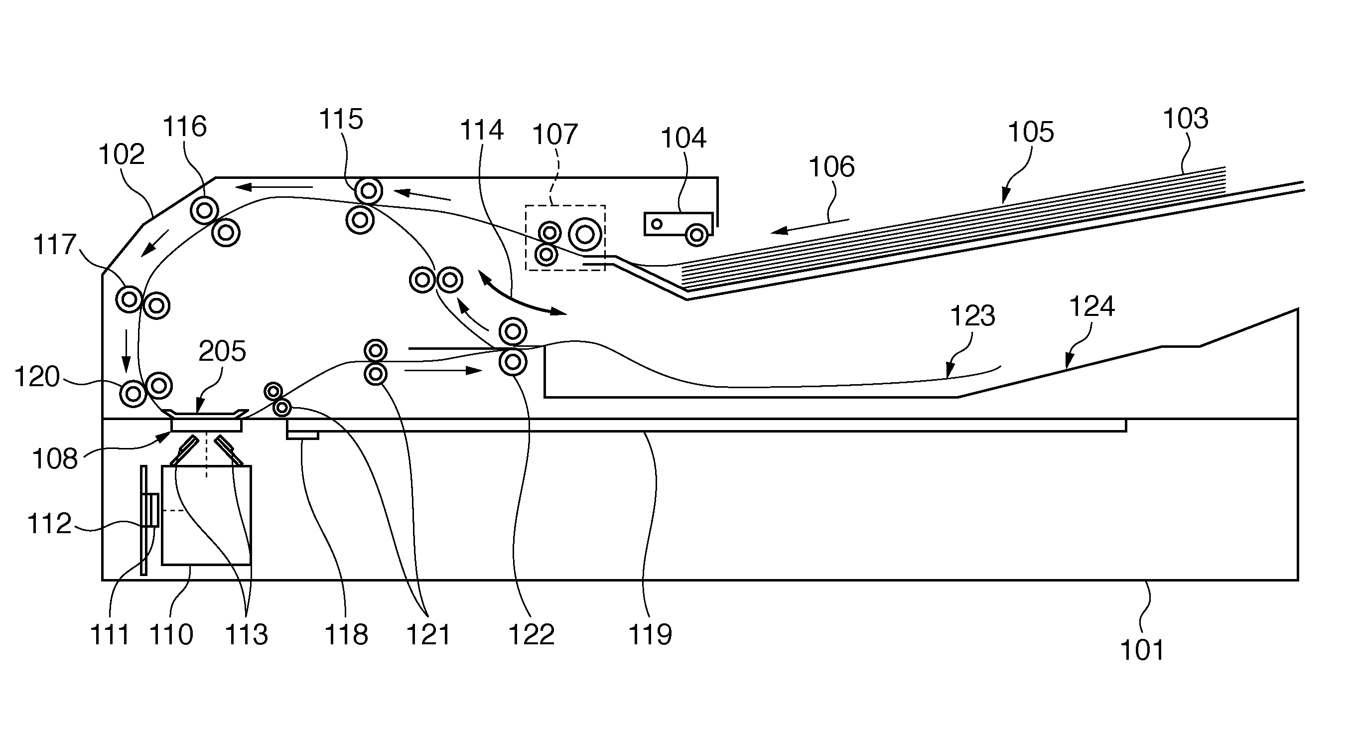
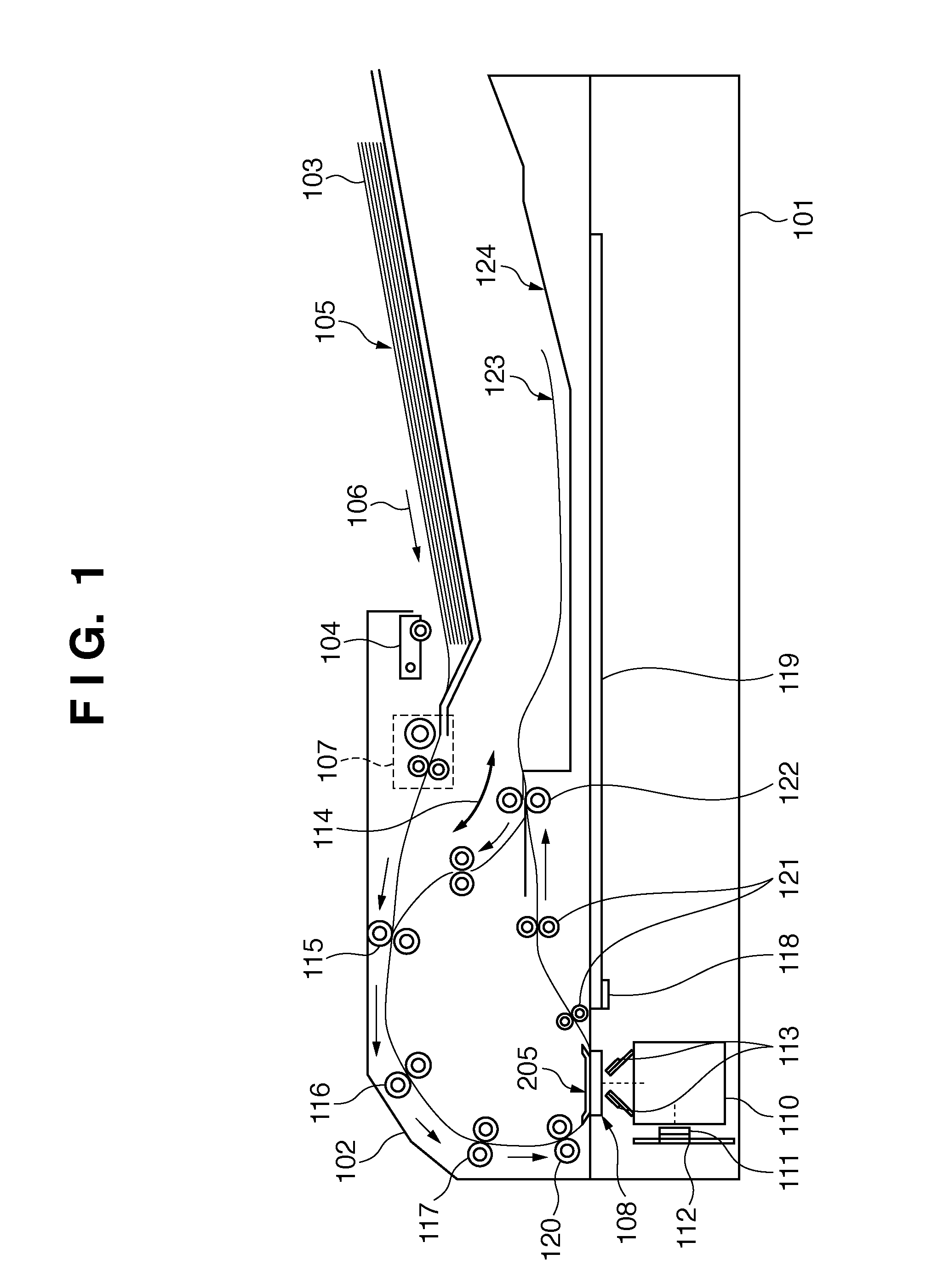
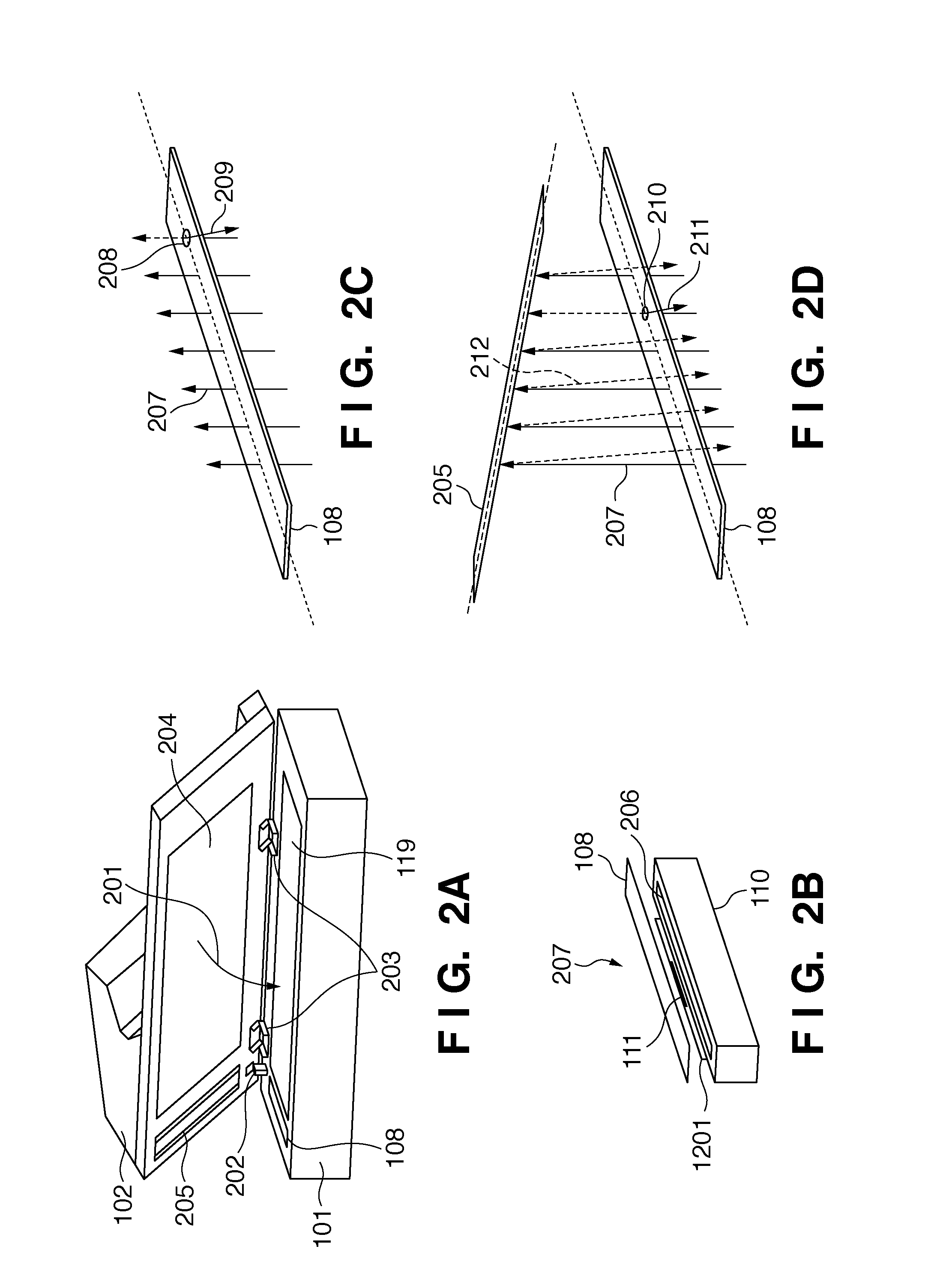
Structure of Image Reading Apparatus Below, an embodiment of the present invention is described in detail with reference to the attached drawings. FIG. 1 is a cross-sectional view of an image reading apparatus that uses two reading methods, namely an original fixed method and a sheet-through method. Note that reading of an original using the sheet-through method is also called “original flow reading”. An image reading apparatus 101 is provided with an original conveying (feeding) unit 102. Originals 103 are set in the original conveying unit 102. The image reading apparatus 101 starts reading an original using an original reading method that is selected via a control means (not shown), in response to a copy button (not shown) being pressed. First, a pickup roller 104 that is controlled by a paper feed motor 619 of the original conveying unit 102 is lowered automatically. Next, a separating / conveying unit 107 starts conveying an original 105, which is the top sheet of the stacked ori...

embodiment 2

[0073]Next, parallel dust detection control is described following steps in the flowchart shown in FIGS. 5A and 5B. Similar to FIGS. 4A and 4B, FIGS. 5A and 5B show the flow of control performed by the CPU 603 that controls detection of white dust on the platen glass 108, black dust thereon, and dust on the white plate 205 using the detection results obtained by the pressure plate sensors 304, 305, and 306 that detect the opening / closing operation of the original conveying unit 102 as a trigger. In FIGS. 4A and 4B, a dust detection sequence is executed in the order of detection of white dust on the platen glass 108, black dust thereon, and dust on the white plate 205 of the original conveying unit 102, and dust detection results are determined in each sequence. In contrast to this, in FIGS. 5A and 5B, detection of black dust on the platen glass 108, and detection of dust on the white plate 205 of the original conveying unit 102 are executed in parallel processing. In this way, dust ...


PUM


Abstract

When an original conveying unit that rotates about a rotation center 901 reaches an opening angle 906, an image is read using a line sensor, and a detected object is determined as being white dust on a platen glass. When it further reaches an opening angle 908, an image is again read using the line sensor, and a detected object is determined as being black dust on the platen glass. When it further reaches an opening angle 910, an image is again read using the line sensor, and a detected object is determined as being dust on a reference white plate with which the original conveying unit is provided in a state of facing a reading position where the line sensor performs reading.

Description

BACKGROUND OF THE INVENTION[0001]1. Field of the Invention[0002]The present invention relates to an image reading apparatus that has optical image reading functionality, such as a FAX, a copying apparatus, or an MFT, for example. In particular, the present invention relates to an image reading apparatus that improves the influence of dust on a platen glass or a white reference plate when performing reading using an original flow reading method with which an original is scanned that is conveyed at a constant speed by an original conveying unit.[0003]2. Description of the Related Art[0004]Image reading apparatuses are broadly divided, based on their reading method, into apparatuses that adopt a sheet-through method, and apparatuses that adopt a fixed original reading method (moving scanner method). The sheet-through method is a method with which an image reading means provided with a line sensor, for instance, is fixed at an original reading position of a platen glass (original platen...

Claims


Application Information

Patent Timeline
IPC IPC(8): H04N1/04
CPCH04N1/00002H04N1/4097H04N1/00037H04N1/00045H04N1/00047H04N1/00063H04N1/00082H04N1/0009H04N1/00572H04N1/00578H04N1/0058H04N1/00602H04N1/0062H04N1/00631H04N1/00681H04N1/00708H04N1/00734H04N1/00779H04N1/00795H04N1/00814H04N1/00013
Inventor KAMEI, MASAFUMI
Owner CANON KK
Learn More