Fuel cell stack

a fuel cell and stack technology, applied in the field of fuel cell stacks, can solve the problems of increasing the cost of fuel cells, and achieve the effect of preventing air retention and easy and reliable discharg

Active Publication Date: 2010-12-09
HONDA MOTOR CO LTD
View PDF2 Cites 18 Cited by
  • Summary
  • Abstract
  • Description
  • Claims
  • Application Information

AI Technical Summary

Benefits of technology

[0014]The present invention has been made to solve the problems of this type, and an object of the present invention is to provide a fuel cell stack which enables air that has entered into the coolant passages to be easily and reliably discharged to the exterior, and which can prevent retention of air in the interior of the fuel cell as much as possible.
[0015]Another object of the present invention is to provide a fuel cell stack which, with an easily and economical structure, reliably cools the entire power generation surface, secures a favorable cross sectional area of the opening for the coolant passages, and enables the separator to be reduced in dimension in the short side (i.e., crosswise) direction of the separator.
[0022]As a result thereof, air that is introduced to the coolant passages can easily and reliably be discharged to the exterior, and retention of air in the interior of the fuel cell can be prevented to the greatest extent possible.
[0024]As a result thereof, air that is introduced to the coolant passages can easily and reliably be discharged to the exterior, and retention of air in the interior of the fuel cell can be prevented to the greatest extent possible.
[0025]Furthermore, according to the present invention, in the coolant supply passages and the coolant discharge passages, connecting passages communicating with a coolant flow field are provided in portions adjacent the short sides of the rectangular separators. Owing thereto, the coolant can be supplied over the entire power generation surface, and by means of a simple and economical structure, the overall power generation surface can be cooled reliably.
[0026]Additionally, the coolant supply passages and the coolant discharge passages are formed across a region, which is greater than the range in which the connecting passages are formed. Accordingly, the cross sectional area of the openings of the coolant supply passages and the coolant discharge passages can be assured favorably, and pressure loss of the coolant can advantageously be reduced. Furthermore, because the coolant supply passages and the coolant discharge passages are constructed as rectangular openings with lengths thereof oriented in the long side direction, the length of the separators can easily be shortened in the short side direction.

Problems solved by technology

Such spacers increase the number of parts required from the fuel cell, the fuel cell overall has an increased dimension in the stacking direction, and costs for the fuel cell are increased.

Method used


Image

  • Fuel cell stack
  • Fuel cell stack
  • Fuel cell stack

Examples


first embodiment

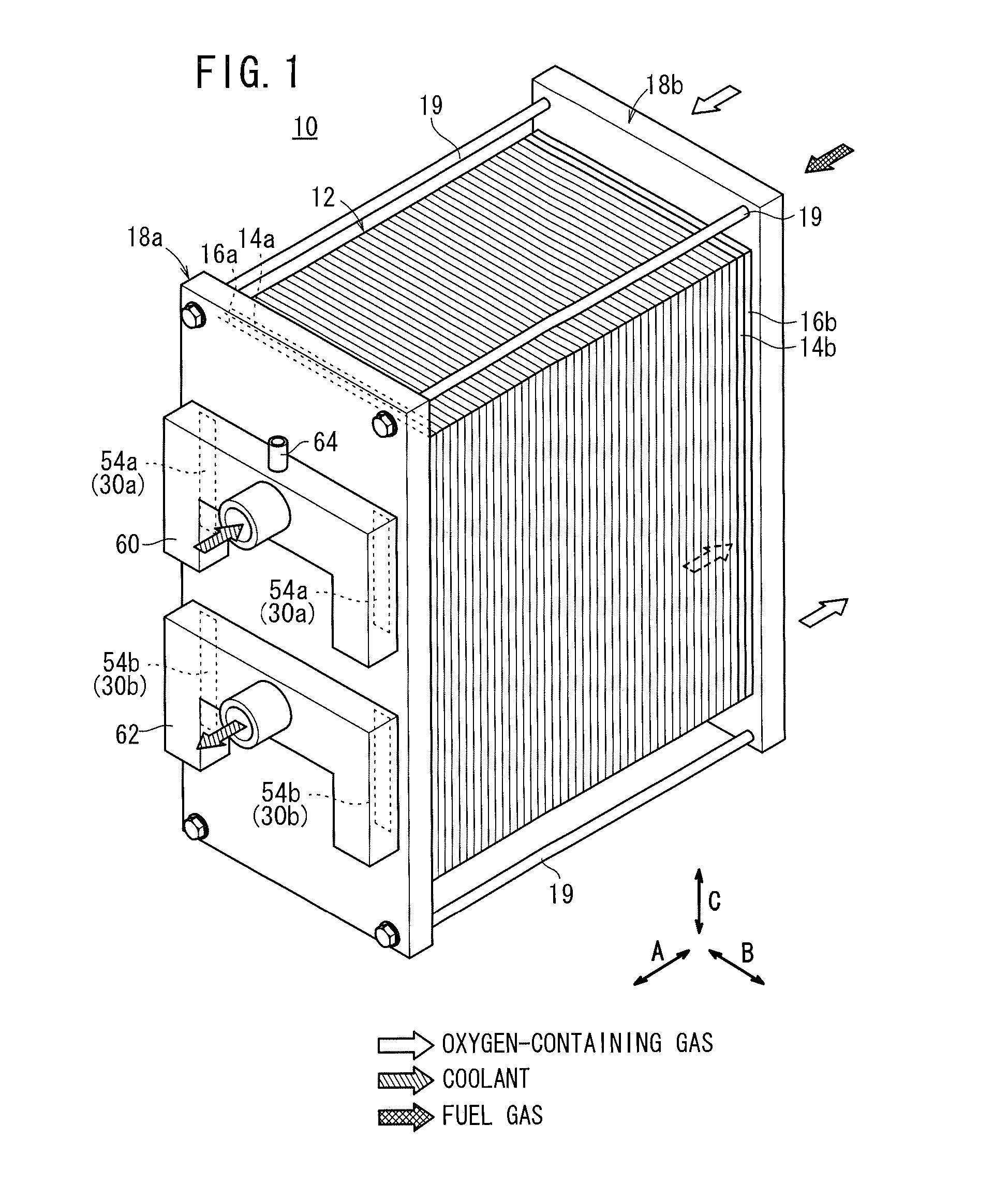
[0048]As shown in FIG. 1, a fuel cell stack 10 according to the present invention is constituted by fuel cells 12, a plurality of such fuel cells 12 being stacked mutually along a horizontal direction (in the direction of the arrow A).

[0049]On one end in the stacking direction of the fuel cells 12, a first terminal plate 14a, a first insulating plate 16a and a first end plate 18a are stacked thereon, whereas on the other end in the stacking direction, a second terminal plate 14b, a second insulating plate 16b and a second end plate 18b are stacked thereon.

[0050]The first end plate 18a and the second end plate 18b, which are constructed with rectangular shapes, are integrally fastened and retained by a plurality of tie rods 19 extending in the direction indicated by A. The fuel cell stack 10 may be retained integrally by a box shaped casing (not shown), which includes the first end plate 18a and the second end plate 18b serving as respective end plates thereof.

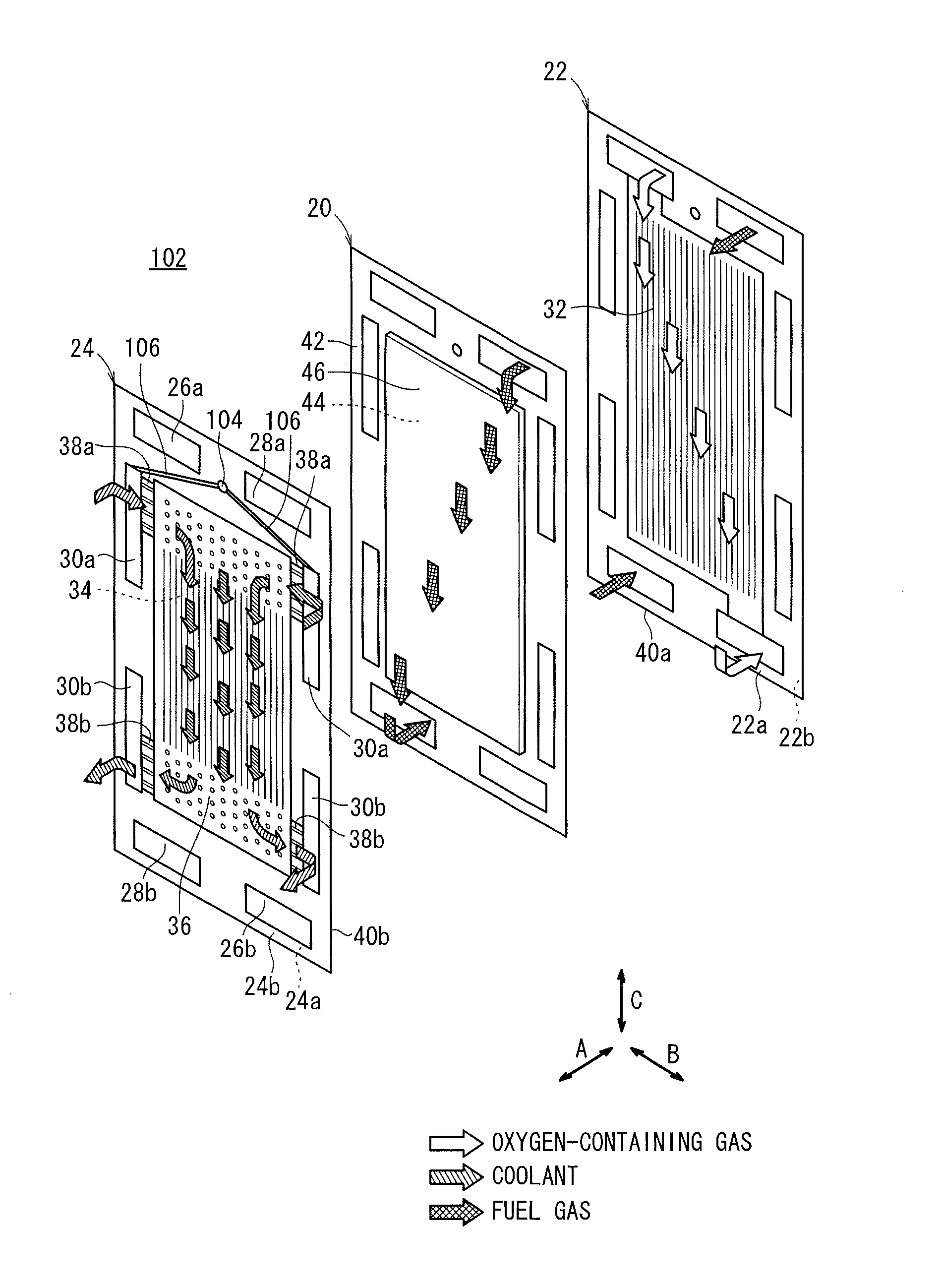
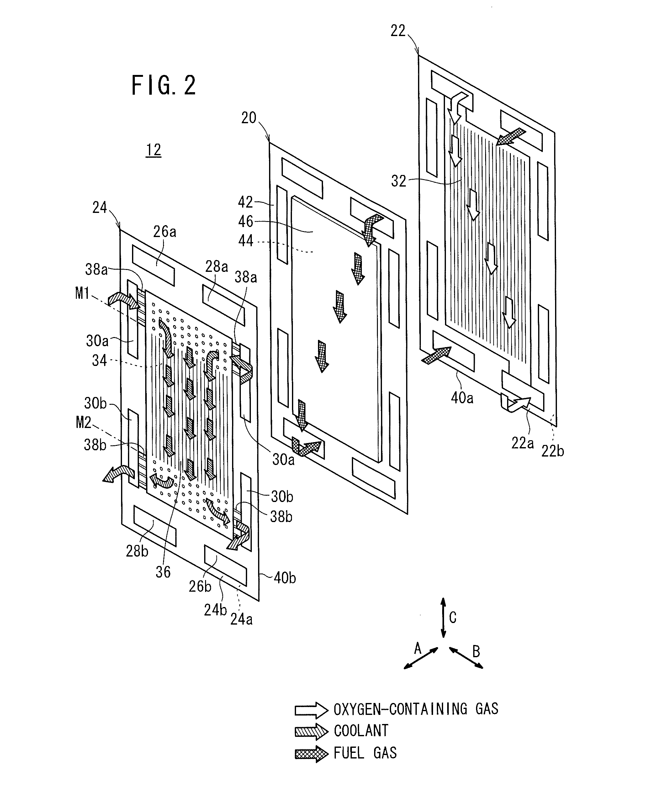
[0051]As shown in FIG. ...

second embodiment

[0088]FIG. 5 is a perspective view with partial omission of a fuel cell stack 70 according to the present invention.

[0089]Structural elements of the second embodiment, which are the same as those of the fuel cell stack 10 according to the first embodiment, are designated by like reference characters and such features shall not be described in detail. Similarly, in the description of the third embodiment or later that follows, detailed explanations of such features are omitted.

[0090]The fuel cell stack 70 is equipped with a first insulating plate 72a and a second insulating plate 72b. In the first insulating plate 72a, a pair of grooves (coolant passage connecting portions) 78a, 78a, which communicate in a vertical direction between the coolant supply passages 30a and the coolant discharge passages 30b, are formed in a surface 76a thereof facing the fuel cell 12.

[0091]Similarly, in a surface 76b of the second insulating plate 72b facing the fuel cell 12, a pair of grooves (coolant pa...

third embodiment

[0093]FIG. 6 is a perspective view with partial omission of a fuel cell stack 90 according to the present invention.

[0094]The fuel cell stack 90 is equipped with at least one separator 92. The separator 92 is constructed substantially in the same manner as the first separator 22 or the second separator 24. For example, the second sealing member 40b provided in the second separator 24 is cut out to form grooves (coolant passage connecting portions) 94 that communicate vertically between the coolant supply passages 30a and the coolant discharge passages 30b. Consequently, with the third embodiment, the same effects as those of the first and second embodiments are attained.


PUM

PropertyMeasurementUnit
dimensionaaaaaaaaaa
pressure lossaaaaaaaaaa
lengthaaaaaaaaaa

Abstract

Coolant supply passages and coolant discharge passages, for example, two respectively thereof, are disposed on upper and lower side portions of a first end plate of a fuel cell stack. Grooves are formed on a surface of the first end plate for establishing communication between each of the coolant supply passages and the coolant discharge passages. Air, which is introduced upwardly of the coolant discharge passages, is discharged to the coolant supply passages.

Description

CROSS-REFERENCE TO RELATED APPLICATION[0001]This application is based upon and claims the benefit of priority from Japanese Patent Applications No. 2009-134577 filed on Jun. 4, 2009, No. 2009-182516 filed on Aug. 5, 2009, No. 2009-184601 filed on Aug. 7, 2009 and No. 2010-102377 filed on Apr. 27, 2010, of which the contents are incorporated herein by reference.BACKGROUND OF THE INVENTION[0002]1. Field of the Invention[0003]The present invention relates to a fuel cell stack in which electrolyte electrode assemblies and separators are stacked in a horizontal direction. Each of the electrolyte electrode assemblies includes a pair of electrodes and an electrolyte interposed between the electrodes.[0004]2. Description of the Related Art[0005]For example, a solid polymer electrolyte fuel cell employs an electrolyte membrane (electrolyte). The electrolyte membrane is a polymer ion exchange membrane. The electrolyte membrane is interposed between an anode and a cathode to form a membrane el...

Claims


Application Information

Patent Timeline
Patent Type & Authority Applications(United States)
IPC IPC(8): H01M8/04
CPCH01M8/0258H01M8/04029Y02E60/50H01M2008/1095H01M8/04074H01M8/241H01M8/2483H01M8/0267H01M8/2457H01M8/2484H01M8/0271
Inventor NAITO, HIDEHARUKOBAYASHI, NORIHISAYOSHITOMI, RYOICHISAKANO, MASAAKISUDA, KEISUKEWATANABE, YASUHIRO
Owner HONDA MOTOR CO LTD
Why Eureka
Try Eureka