Fuel cell

a fuel cell and fuel gas technology, applied in the field of fuel cells, can solve the problems of fuel gas and oxygen-containing gas not flowing smoothly, water may stagnate, power generation performance may be lowered undesired, etc., and achieve the effect of reducing buffer areas effectively, facilitating and reliably dischargeing, and ensuring the desired power generation performan

Active Publication Date: 2012-04-19
HONDA MOTOR CO LTD
View PDF4 Cites 12 Cited by
  • Summary
  • Abstract
  • Description
  • Claims
  • Application Information

AI Technical Summary

Benefits of technology

[0013]In the present invention, the continuous linear guide ridges are provided in the buffer. The linear guide ridges include the bent portions, and have different lengths in a stepwise manner. Thus, the reactant gas does not flow around water produced in the power generation reaction. In the structure, by the reactant gas, the water produced in the power generation reaction is easily and reliably discharged. Also, the reactant gas can be supplied uniformly, and a desired power generation performance can be maintained suitably. Further, the areas of the buffer can be reduced effectively, and the overall size of the fuel cell can be reduced easily.

Problems solved by technology

As a result, the fuel gas and the oxygen-containing gas may not flow smoothly, and thus the power generation performance may be lowered undesirably.
Further, in the case where water flows into the fuel cell stack from the outside, the water may stagnate therein, and cannot be discharged from the fuel cell stack.
As a result, the power generation performance may be lowered undesirably.

Method used


Image

  • Fuel cell
  • Fuel cell
  • Fuel cell

Examples


first embodiment

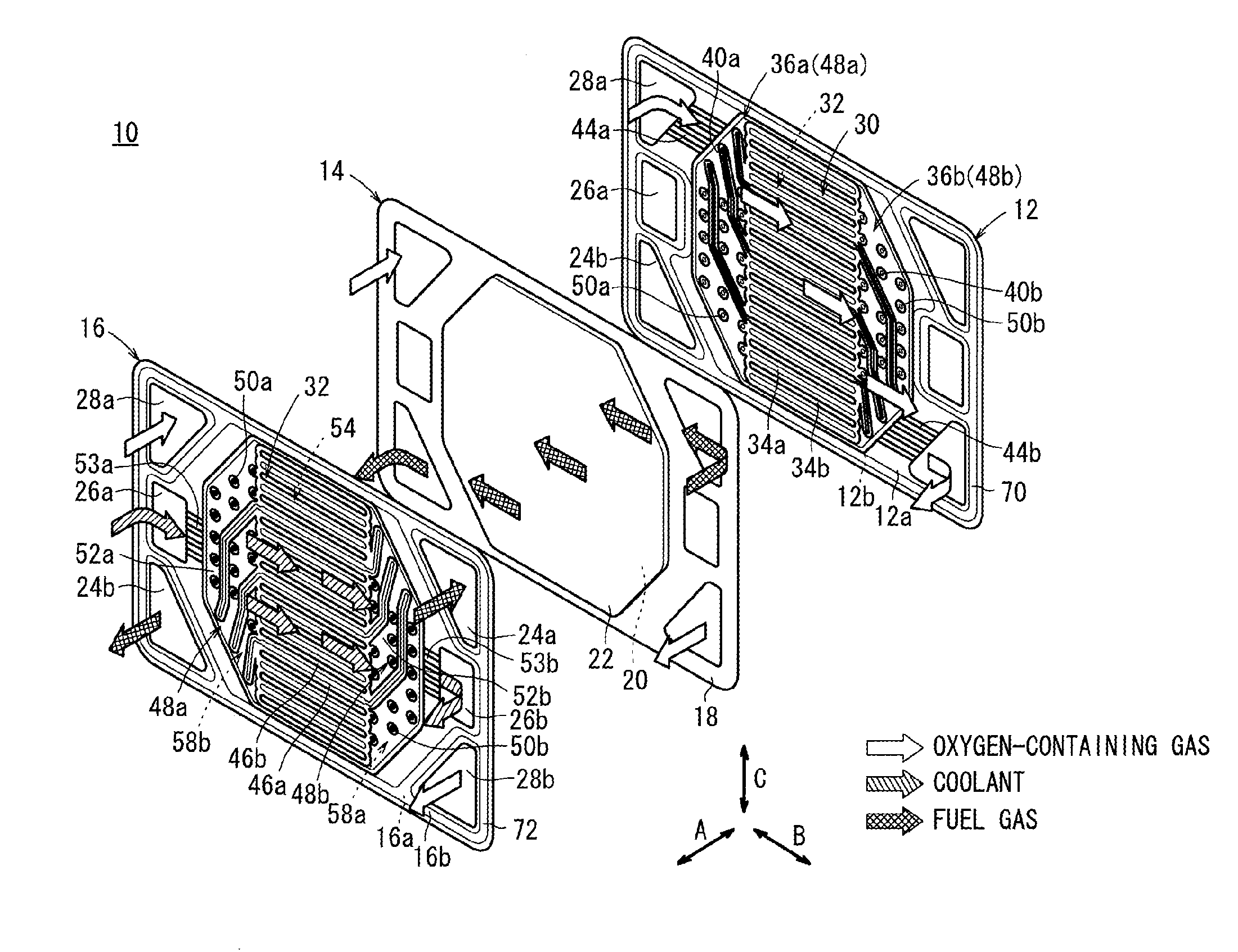
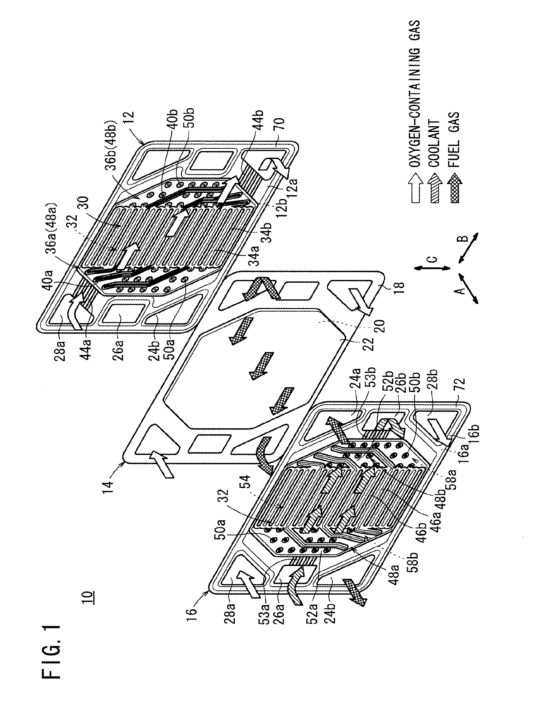
[0024]As shown in FIG. 1, a fuel cell 10 according to the present invention includes a cathode-side metal separator 12, a membrane electrode assembly (electrolyte electrode assembly) (MEA) 14, and an anode-side metal separator 16.

[0025]For example, the cathode-side metal separator 12 and the anode-side metal separator 16 are made of steel plates, stainless steel plates, aluminum plates, plated steel sheets, or metal plates having anti-corrosive surfaces by surface treatment. The cathode-side metal separator 12 and the anode-side metal separator 16 are formed by pressing metal thin plates into corrugated plates to have ridges and grooves in cross section.

[0026]For example, the membrane electrode assembly 14 includes a cathode 20, an anode 22, and a solid polymer electrolyte membrane (electrolyte) 18 interposed between the cathode 20 and the anode 22. The solid polymer electrolyte membrane 18 is formed by impregnating a thin membrane of perfluorosulfonic acid with water, for example.

[...

second embodiment

[0079]In the second embodiment, the continuous guide flow fields 96a, 96b protruding toward the fuel gas flow field 84 side are formed in the inlet buffer 90a and the outlet buffer 90b on the surface 82a of the intermediate metal separator 82. Therefore, the fuel gas does not flow around the water produced in the power generation reaction.

[0080]Further, the embossed flow fields 104a, 104b protruding toward the oxygen-containing gas flow field 86 side are formed in the inlet buffer 100a and the outlet buffer 100b, on the surface 82b of the intermediate metal separator 82. Thus, in the oxygen-containing gas flow field 86, the oxygen-containing gas flows smoothly without any influence by the shapes of the back side of the continuous guide flow fields 96a, 96b.


PUM

PropertyMeasurementUnit
lengthsaaaaaaaaaa
height areaaaaaaaaaaa
heightaaaaaaaaaa

Abstract

An oxidant gas conduit communicating with both an oxidant gas inlet communication hole and an oxidant gas outlet communication hole is formed in a surface of a cathode-side metallic separator which forms a fuel cell. Continuous linear guide ridges which protrude from intermediate height sections to the oxidant gas conduit side and form continuous guide conduits are provided on the cathode-side metallic separator. The linear guide ridges are continuously connected to ends of rectilinear conduit ridges which form rectilinear conduits, are provided with bend portions, and are set to lengths which are different from each other in a step-like manner.

Description

TECHNICAL FIELD[0001]The present invention relates to a fuel cell formed by stacking an electrolyte electrode assembly and a metal separator in the form of a corrugated plate in a stacking direction. The electrolyte electrode assembly includes electrodes and an electrolyte interposed between the electrodes. A reactant gas flow field as a passage of a fuel gas or an oxygen-containing gas is formed on one surface of the metal separator. A reactant gas passage for the fuel gas or the oxygen-containing gas extends through the fuel cell in the stacking direction.BACKGROUND ART[0002]For example, a solid polymer electrolyte fuel cell employs an electrolyte membrane. The electrolyte membrane is a polymer ion exchange membrane. The electrolyte membrane is interposed between an anode and a cathode to form a membrane electrode assembly (MEA). The membrane electrode assembly is sandwiched between a pair of separators to form a unit cell for generating electricity. In use, normally, a predetermi...

Claims


Application Information

Patent Timeline
Patent Type & Authority Applications(United States)
IPC IPC(8): H01M8/10H01M8/04
CPCH01M8/0206H01M8/0247Y02E60/521H01M8/1002H01M8/0258H01M8/1007Y02E60/50Y02E60/10Y02P70/50H01M8/2483H01M8/241H01M8/0267H01M8/2457H01M10/14H01M8/0202H01M10/0585H01M8/026H01M8/0265H01M50/46
Inventor SUGIURA, SEIJISATO, SHUJITAKAI, TAKAHIROWATANABE, YASUHIRO
Owner HONDA MOTOR CO LTD
Why Eureka
Try Eureka