Exhaust gas purification device

a technology of exhaust gas and purification device, which is applied in the direction of machines/engines, lighting and heating apparatus, separation processes, etc., can solve the problems of limited space of the vehicle body where the exhaust gas purification device is provided, and achieve the effect of simple configuration

Active Publication Date: 2013-03-14
ISUZU MOTORS LTD +1
View PDF2 Cites 18 Cited by
  • Summary
  • Abstract
  • Description
  • Claims
  • Application Information

AI Technical Summary

Benefits of technology

[0014]With an exhaust gas purification device according to the present invention, a reduction agent, which is injected from a reduction agent supply means, can be prevented from being retained at the peripheral edge of an opening section provided on an exhaust pipe, and peripheral edge of the opening section can be effectively prevented from being corroded by the retained reduction agent with a simple configuration.

Problems solved by technology

However, space of a vehicle body wherein the exhaust gas purification device being provided is limited.

Method used


Image

  • Exhaust gas purification device
  • Exhaust gas purification device
  • Exhaust gas purification device

Examples


Embodiment Construction

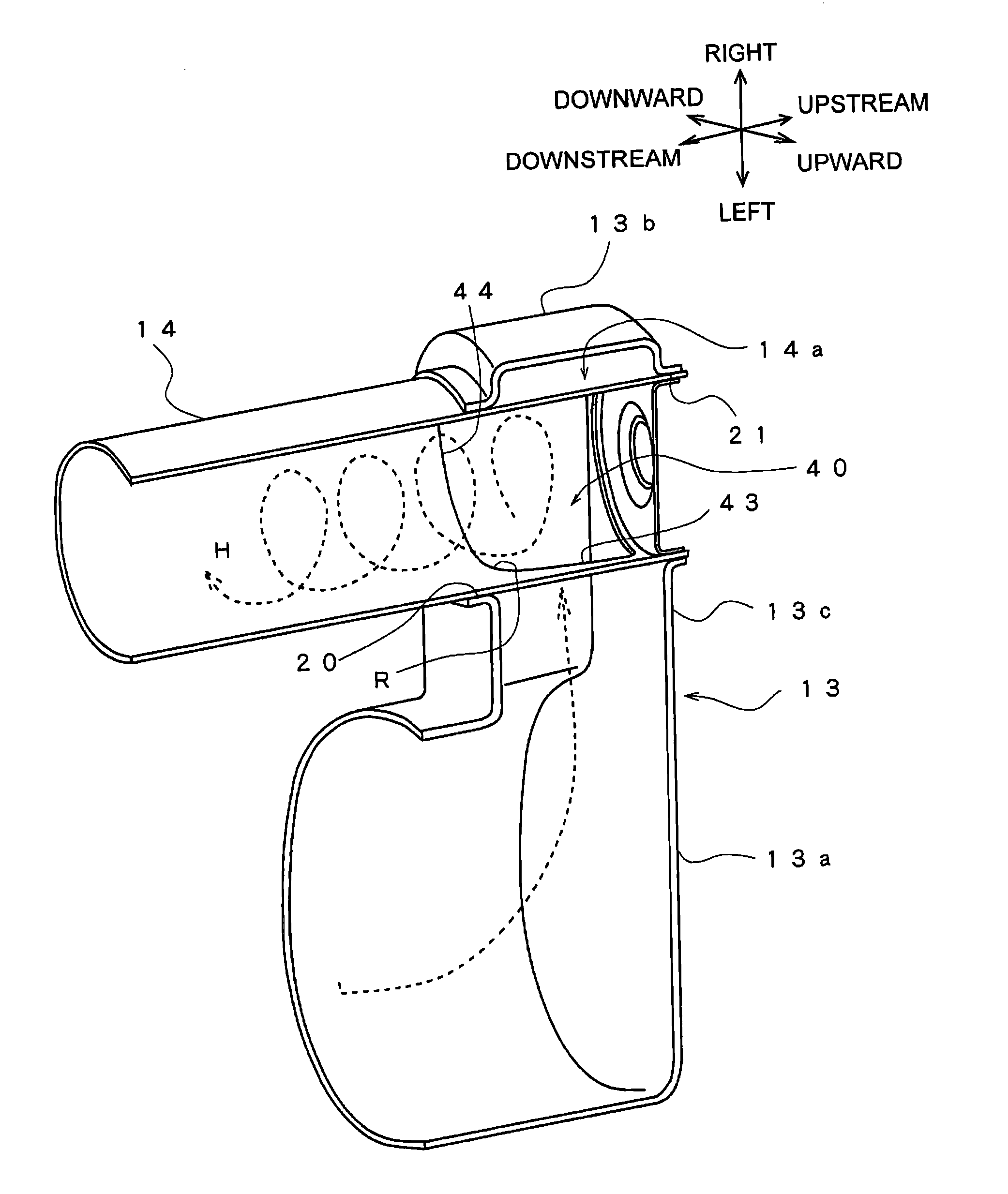
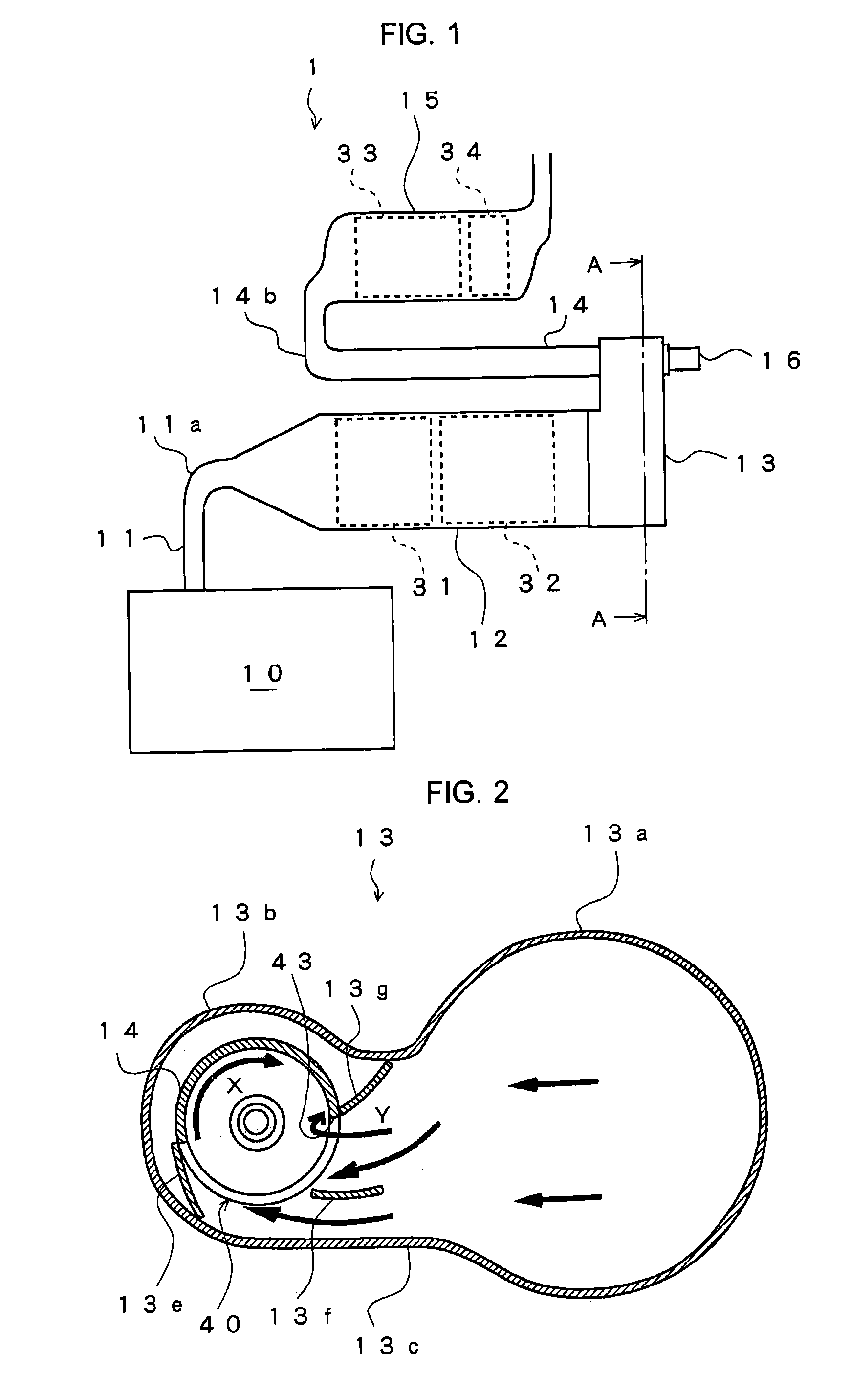
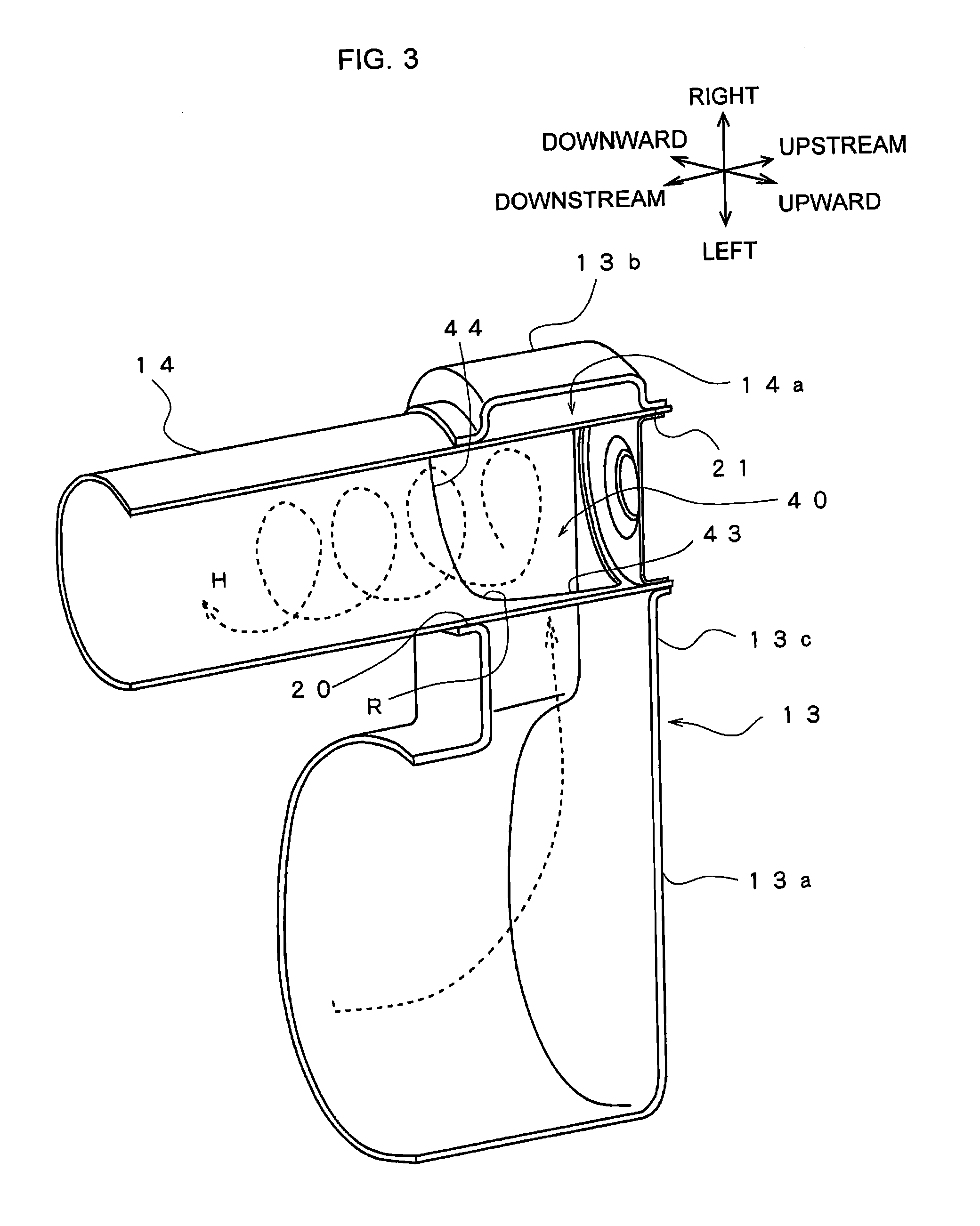
[0022]An exhaust gas purification device according to an embodiment of the present invention will be described below with reference to the FIGS. 1 to 5. Identical components have been allocated identical reference numerals and have identical names and functions. Accordingly, detailed description of these components will not be repeated.

[0023]As shown in FIG. 1, the exhaust gas purification device 1 includes, in order from the upstream side, an internal combustion engine of a diesel engine (hereinafter, engine) 10, a connection pipe 11 for leading exhaust gas from the engine 10, an upstream post-processing device 12 having provided therein an upstream oxidation catalyst (hereinafter, upstream DOC) 31 and a diesel particulate filter (hereinafter, DPF) 32, a mixing chamber 13 being positioned the longitudinal direction thereof approximately 90 degrees relative to the upstream post-processing device 12, an exhaust pipe (second exhaust pipe) 14 having provided on the upstream end thereof...


PUM

PropertyMeasurementUnit
radiusaaaaaaaaaa
densityaaaaaaaaaa
temperatureaaaaaaaaaa

Abstract

An exhaust gas purification device with a first exhaust pipe section for leading exhaust gas discharged from an engine, a second exhaust pipe section having in a side section on an upstream side thereof an opening section for introducing exhaust gas from the first exhaust pipe section, the second exhaust pipe section being connected at a side section thereof to the first exhaust pipe section so that flow of exhaust gas therein becomes a swirl flow and having provided on a downstream side thereof a post-processing device, and a reduction agent supply device provided at an upstream end of the second exhaust pipe section. The opening section is formed so as to include at least a first tilted side extending in a direction tilted relative to an axis of the second exhaust pipe section.

Description

TECHNICAL FIELD[0001]The present invention relates to an exhaust gas purification device that includes a post-processing device for reducing and purifying nitrogen compounds contained in exhaust gas discharged from an internal combustion engine, using a reduction agent to be supplied.BACKGROUND ART[0002]A selective reduction NOx catalyst (hereinafter, SCR) and an occlusion reduction NOx catalyst (hereinafter, LNT), for example, are well known as a post-processing device that reduces and purifies nitrogen compounds (hereinafter, NOx) contained in exhaust gas discharged from a diesel engine (internal combustion engine).[0003]In the SCR, the NOx in the exhaust gas can be reduced and purified by promoting the reductive reaction of the NOx with ammonia (NH3) that is supplied as a reduction agent. In the LNT, the NOx in the exhaust gas is occluded when an air-fuel ratio of the exhaust gas is lean. On the other hand, when the air-fuel ratio is raised by unburned fuel (HC) that is supplied ...

Claims


Application Information

Patent Timeline
Patent Type & Authority Applications(United States)
IPC IPC(8): B01D53/92
CPCF01N3/103F01N3/2066F01N3/2892F01N2240/20F01N13/0097F01N2610/02F01N2610/1453B01D53/92F01N13/009F01N2470/18B01F25/103B01F2025/931B01F25/3131
Inventor KAGEYAMA, YUUTAOHARA, ISAO
Owner ISUZU MOTORS LTD
Why Eureka
Try Eureka