Work vehicle

Active Publication Date: 2017-08-03
YANMAR POWER TECHNOLOGY CO LTD
View PDF37 Cites 18 Cited by
  • Summary
  • Abstract
  • Description
  • Claims
  • Application Information

AI Technical Summary

Benefits of technology

[0021]In the one aspect of the present invention, the work vehicle may further include a hood, an engine, a cooling fan, a plurality of heat exchangers, and a bottom plate. The hood may be configured to cover an engine compartment disposed at a front section of a travelling machine body. The engine may be a drive source. The cooling fan may be configured to cool the engine. The plurality of heat exchangers may be configured to allow cooling air guided by the cooling fan to pass through the heat exchangers to exchange heat with a cooling medium. The bottom plate may cover an upper surface of a front section of the travelling machine body. The hood and the bottom plate may include opening portions at positions forward of the cooling fan. The hood and the bottom plate may be configured to introduce cooling air into the hood through the opening portions when the cooling fan is driven. With this configuration, in the limited configuration at the front of the cooling fan, the open area is made greater than the flow rate of air to be passed through the cooling fan. This configuration reduces the flow velocity of the cooling air to be passed through the cooling fan, and the cooling air in the engine compartment is optimally controlled. Since the meshed opening portion is also provided on the bottom plate, dust is prevented from entering the engine compartment and allowed to fall down by its own weight after the engine is stopped.
[0022]The left and right front frames and the left and right rear frames may be coupled in the fore-and-aft direction, and the front ends of the left and right front frames may be held by a coupling member made of a rectangular metal casting to configure the travelling machine body. The opening portion of the bottom plate may be located at a position above the coupling member. Since the coupling member of the travelling machine body is located below the opening portion of the bottom plate, when the outside air flows into the engine compartment through the opening portion, the coupling member prevents dust and mud from entering the engine compartment. Since the front frames, which support the engine, are secured by the coupling member, which is made of a metal casting, the support structure of the engine is reinforced.
[0023]According to the embodiment of the invention of the present application, covering the side of the engine w

Problems solved by technology

If the DPF is mounted apart from the engine, the temperature of exhaust gas supplied from the engine to the DPF is decreased, and regeneration of a soot filter, or a like member, of the DPF is likely to be incomplete.
Unfortunately, a special method is required to increase the temperature of the exhaust gas in the DPF to regenerate the soot filter, or the like member.
Since the support structure of the DPF, however, is not easily simplified, the workability in mounting the DPF or shock proof cannot be improved.
Increase in the size of the engine due to mounting of the DPF increases influence caused by vibration of the engine having different vibration systems, and breakage or fai

Method used


Image

  • Work vehicle
  • Work vehicle
  • Work vehicle

Examples


Example

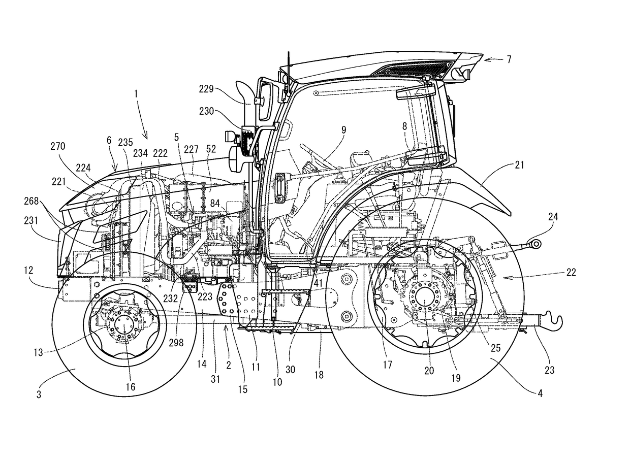
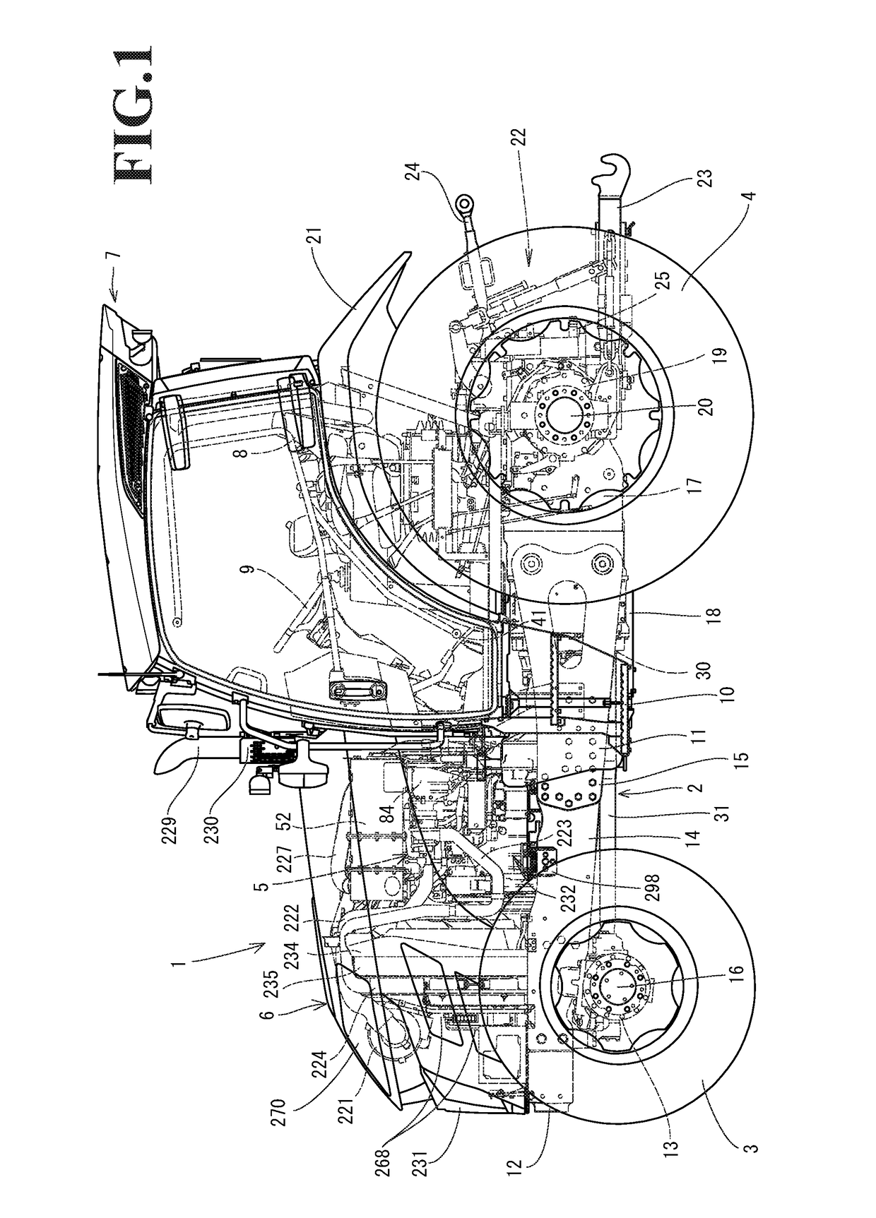
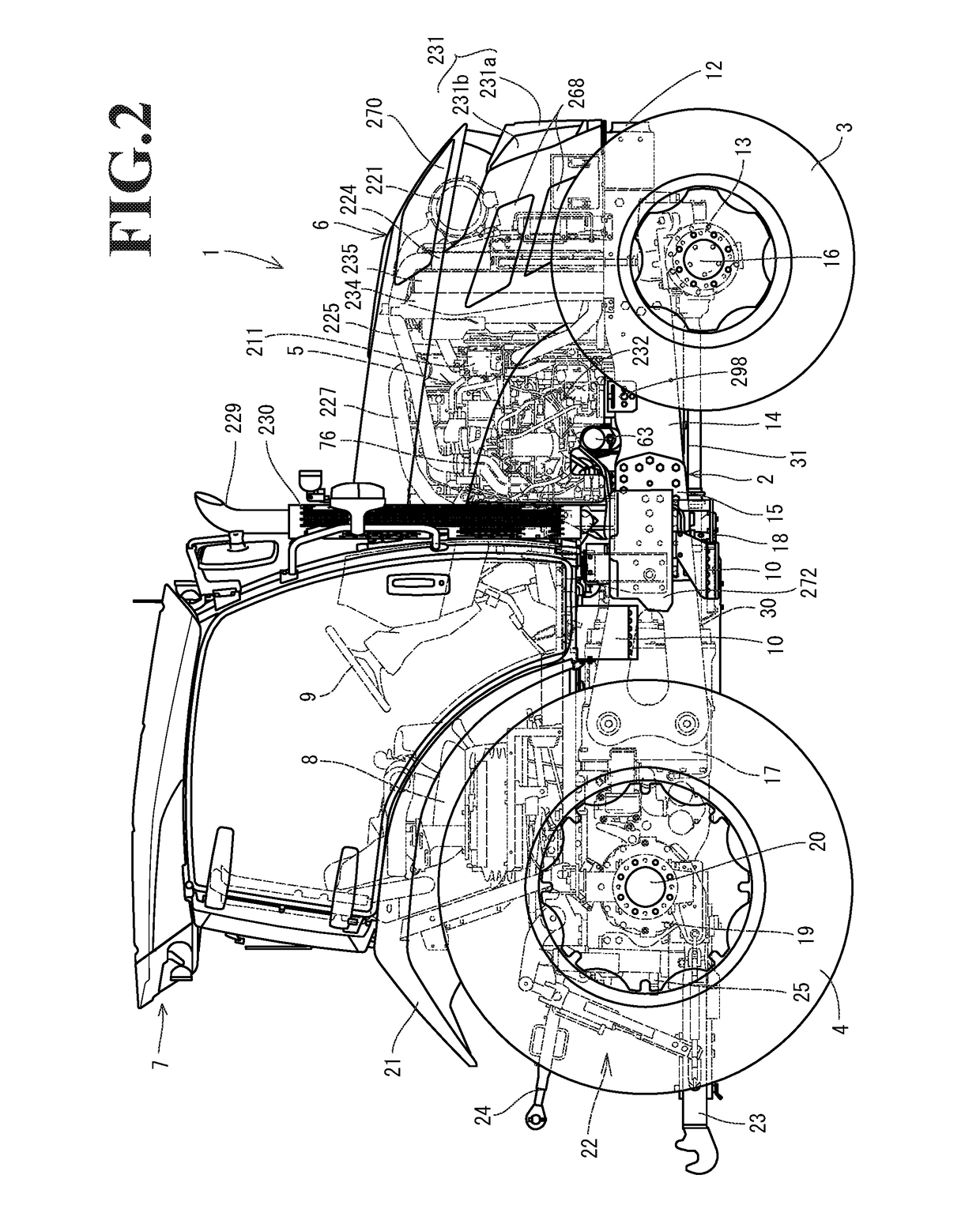
[0068]Hereinafter, an embodiment of the present invention will be described with reference to the drawings. First, a configuration of a tractor 1 according to the embodiment will be described with reference to FIGS. 1 to 22. The tractor 1 is a work vehicle. The tractor 1 of this embodiment includes a travelling machine body 2. The travelling machine body 2 is supported by travelling sections. The travelling sections are a pair of left and right front wheels 3 and a pair of left and right rear wheels 4 in this embodiment. The rear wheels 4 and the front wheels 3 are driven by a power source mounted on the front section of the travelling machine body 2. The power source is a common rail diesel engine 5 (hereinafter, simply referred to as the engine) in this embodiment. The tractor 1 travels forward and backward by driving the rear wheels 4 and the front wheels 3. The engine 5 is covered with a hood 6. A cabin 7 is provided on the upper surface of the travelling machine body 2. An oper...


PUM


Abstract

A work vehicle includes an engine, a post-processing device, and a cooling fan. The engine is mounted on a front portion of a travelling machine body. The post-processing device purifies exhaust gas of the engine. The cooling fan water-cools the engine. The cooling fan is located in front of the engine. The cooling fan, the engine, and the post-processing device are covered with a hood. The hood includes a shield. The shield covers a lower section of the post-processing device and one side of the engine. The shield is a perforated plate including a plurality of holes.

Description

CROSS-REFERENCE TO RELATED APPLICATIONS[0001]The present application is a continuation application of International Application No. PCT / JP2015 / 078379, filed Oct. 6, 2015, which claims priority to Japanese Patent Application No. 2014-211132, filed Oct. 15, 2014 and Japanese Patent Application No. 2015-079706, filed Apr. 9, 2015. The contents of these applications are incorporated herein by reference in their entirety.BACKGROUND OF THE INVENTION[0002]The invention of the present application relates to work vehicles.[0003]As higher-level emission regulations have been applied to diesel engines (hereinafter, simply referred to as engines), agricultural vehicles and construction and civil engineering machines that include an engine are required to include an exhaust-gas purification device that removes air pollutants in exhaust gas. Diesel particulate filters (hereinafter, referred to as the DPF) that collect, for example, particulate matter in exhaust gas (for example, refer to Japanese...

Claims


Application Information

Patent Timeline
IPC IPC(8): F01N3/08B60K13/04B62D25/10B60K11/02F01N13/00F01N13/10F02M26/22F01P5/06F01P11/02B60K11/06F01P5/02
CPCF01N3/08B60K11/06B60K13/04B62D25/10B60K11/02F01N13/008F01N13/102F02M26/22F01P5/06F01P11/02F01P5/02F01N13/14F02B77/11B60K13/06B62D21/186B62D49/06F01N13/08F01N2260/20F01N2340/04F01N2590/08F01P2001/005F01N3/24F01N3/28B60Y2200/415B60Y2200/221
Inventor KUROKAWA, YOSHIAKIHASEGAWA, SATOSHIADACHI, MASAHITO
Owner YANMAR POWER TECHNOLOGY CO LTD
Why Eureka
Try Eureka