A nozzle for a vacuum cleaner

Active Publication Date: 2017-01-12
KONINKLJIJKE PHILIPS NV
View PDF0 Cites 33 Cited by
  • Summary
  • Abstract
  • Description
  • Claims
  • Application Information

AI Technical Summary

Benefits of technology

[0034]Air channels help to guide the air flow entering from the edge of the nozzle to the suction aperture. Air channels help to reduce the amount that air flow entering impinges with other air flow. Therefore, air channels may aid in reducing turbulence.
[0035]Adjacent flexible flaps may define an inlet to the secondary air channel. Therefore, the flexible flaps are able to help guide air flow and detritus directly into the secondary air channel.
[0036]A raised section of

Problems solved by technology

However, V-shaped protrusions are inherently rigid and so result in poor performance on uneven s

Method used


Image

  • A nozzle for a vacuum cleaner
  • A nozzle for a vacuum cleaner
  • A nozzle for a vacuum cleaner

Examples


Example

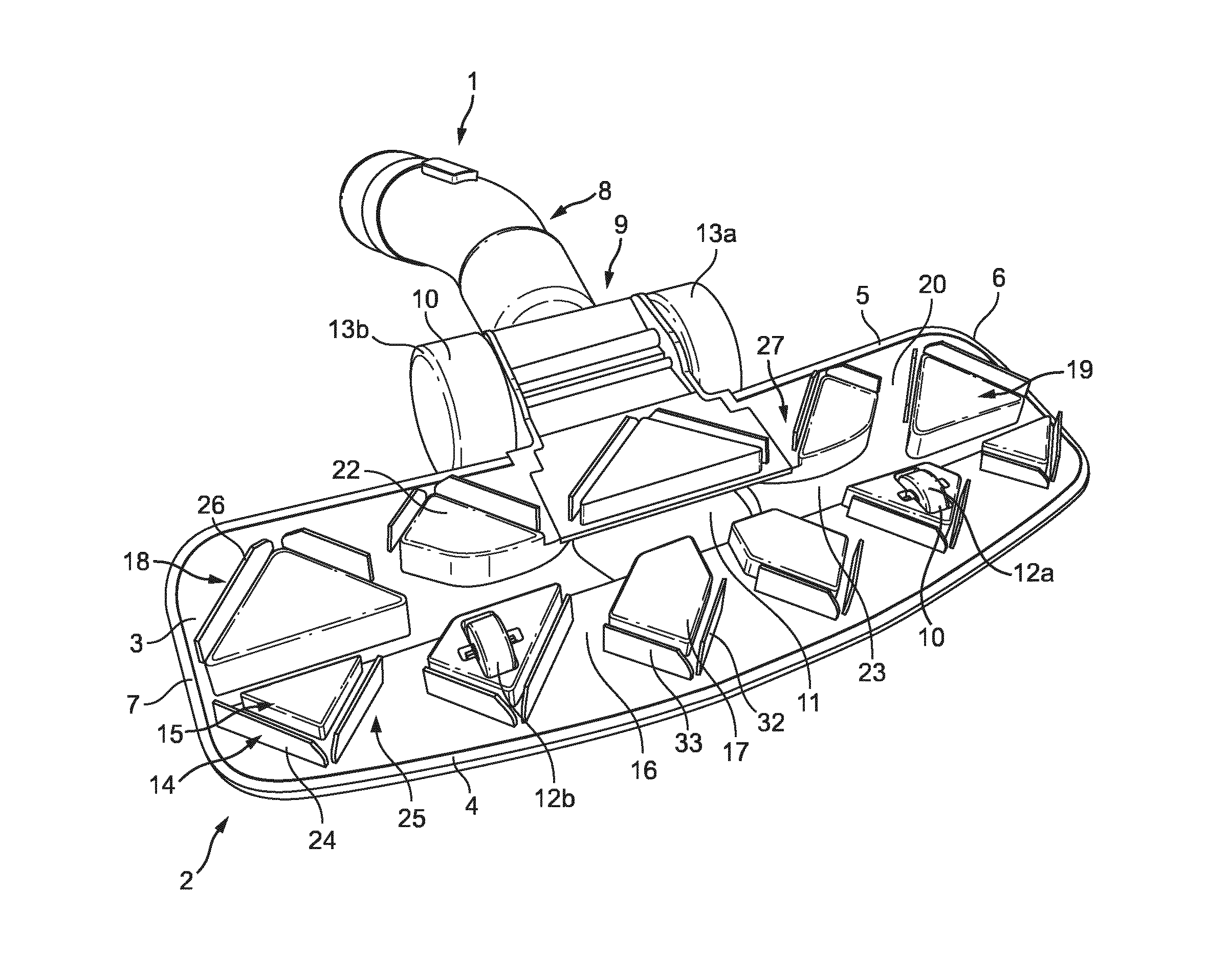
[0060]Referring to FIG. 1, there is shown a nozzle 1 for a vacuum cleaner (not shown). The vacuum cleaner is configured to remove detritus, such as food, dirt, and hair, from a surface to be cleaned (not shown). Surfaces to be cleaned include, but are not limited to, hard floors, such as hard wood flooring, or planks, and tiles.

[0061]A vacuum cleaner may have different configurations, for example, an upright vacuum cleaner, or a handheld vacuum cleaner.

[0062]The nozzle 1 comprises a body 2 having a base 3. The base 3 forms the underside of the body 2. The base 3 is disposed proximate to a surface to be cleaned when the nozzle 1 is in use. The nozzle 1 for a vacuum cleaner is fluidly connectable to a suction unit (not shown) via a suction hose, although it will be understood that alternative arrangements are possible. For example, the suction unit (not shown) may be mounted to an upper end of the body 2.

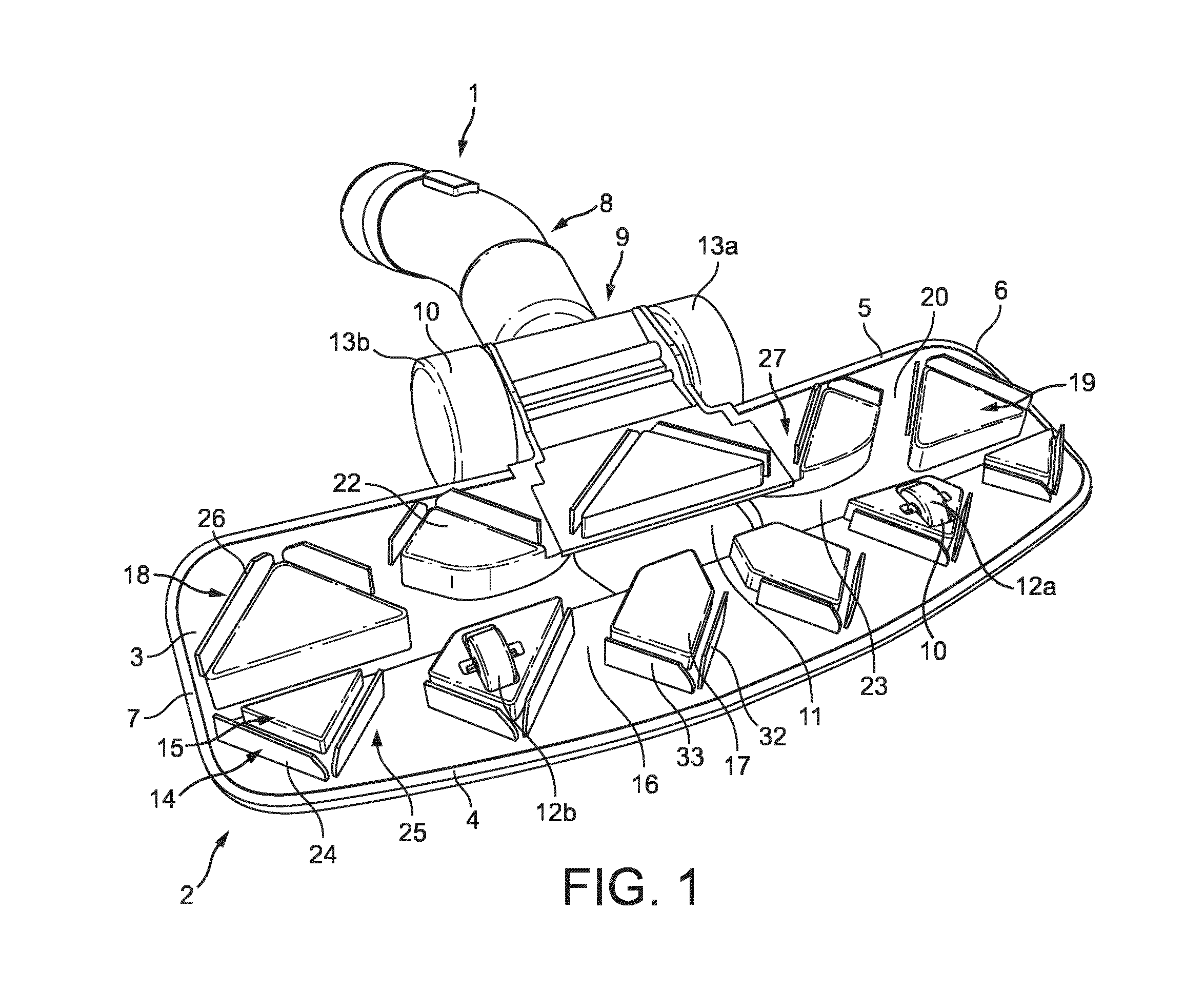
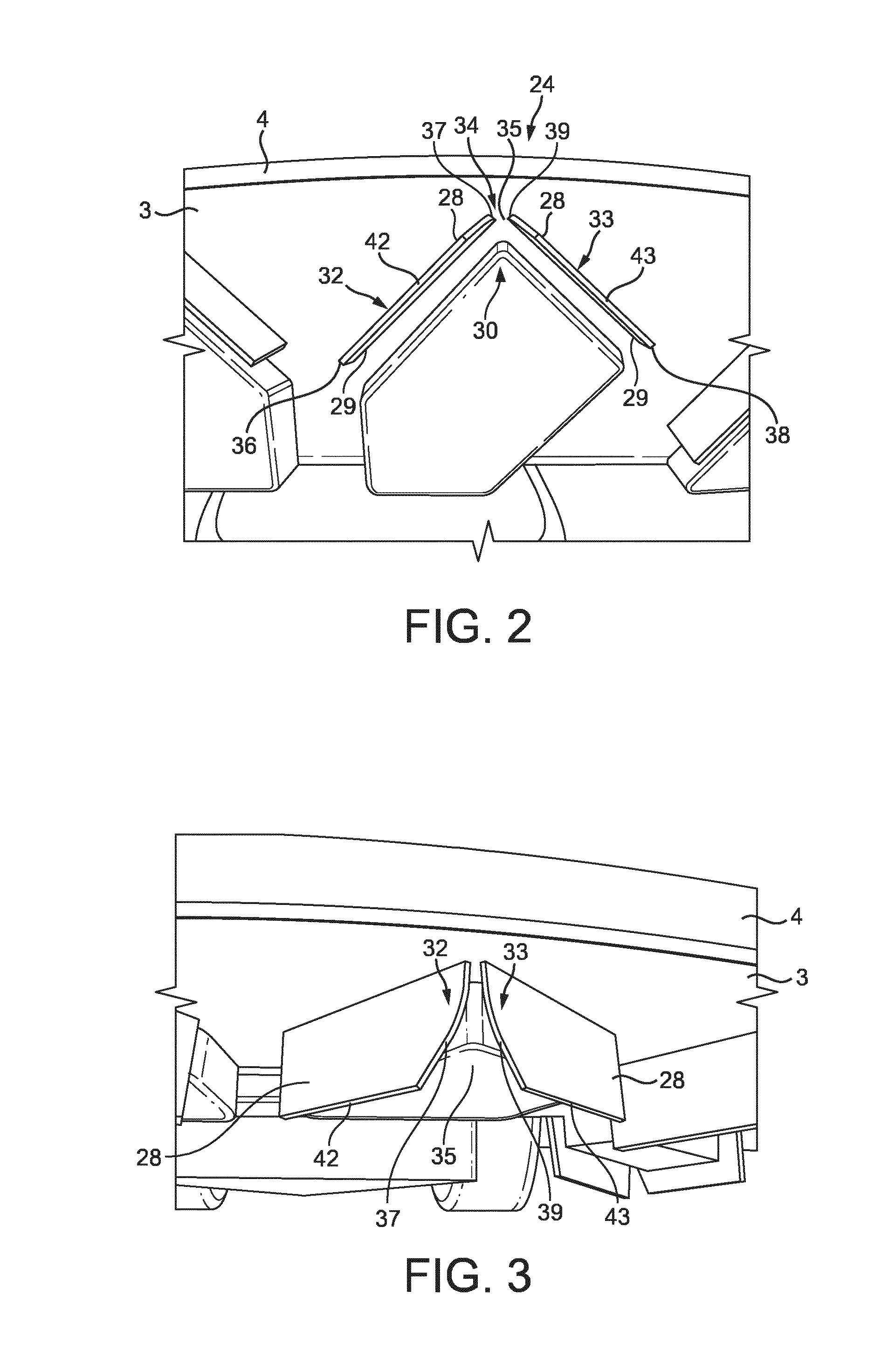
[0063]In the present embodiment, the base 3 has front and rear edges 4, 5. The fr...


PUM


Abstract

The present invention relates to a nozzle (1) for a vacuum cleaner. The nozzle (1) has a base (3) having an edge (4, 5) and a suction aperture (11) in the base (3). At least one flexible flap (24, 26) protrudes from the base (3) between the edge (4, 5) and the suction aperture (11). The flexible flap (24, 26) has first and second sections (32, 33) separable by an opening (35). The first and second sections (32, 33) are urged towards each other when the nozzle (1) is moved in a first direction in which the edge (4, 5) is a leading edge to close the opening (35) or tend the opening (35) towards closure, and the first and second sections (32, 33) are biased away from each other when the nozzle (1) is moved in a second direction in which the edge (4, 5) is a trailing edge to open the opening (35) or to further open the opening. The present invention also relates to a vacuum cleaner comprising a nozzle (1) for a vacuum cleaner.

Description

FIELD OF THE INVENTION[0001]The present invention relates to a nozzle for a vacuum cleaner.BACKGROUND OF THE INVENTION[0002]Vacuum cleaners are commonplace in households and places of work. Vacuum cleaners are generally used to remove detritus, such as food, dirt, and hair, from a surface, such as a floor. A common type of vacuum cleaner generally comprises a motor that drives a fan which sucks air through a suction aperture in a maneuverable nozzle which causes a decrease in pressure at the surface to be cleaned. Air is drawn along the surface to be cleaned and into the suction aperture carrying detritus which is transported into a collection vessel for removal.[0003]Many vacuum cleaners include brush elements which protrude from the base of the nozzle. As the shape and size of the detritus varies from small dust particles to larger pieces of food, it is common to provide spaces between the brush elements to allow detritus to pass the protrusions and enter the vacuum cleaner.[0004]...

Claims


Application Information

Patent Timeline
IPC IPC(8): A47L9/02
CPCA47L9/02A47L9/0606A47L9/06
Inventor KLEINE-DOEPKE, BASTIAN CORNELISDE WIT, BASTIAAN JOHANNESWESSELS, ARNOLDUS CORNELIS
Owner KONINKLJIJKE PHILIPS NV
Why Eureka
Try Eureka