
Radio frequency coxial connector

Active Publication Date: 2010-12-09
ADVANCED CONNECTEK INC
View PDF7 Cites 5 Cited by
  • Summary
  • Abstract
  • Description
  • Claims
  • Application Information

AI Technical Summary

Benefits of technology

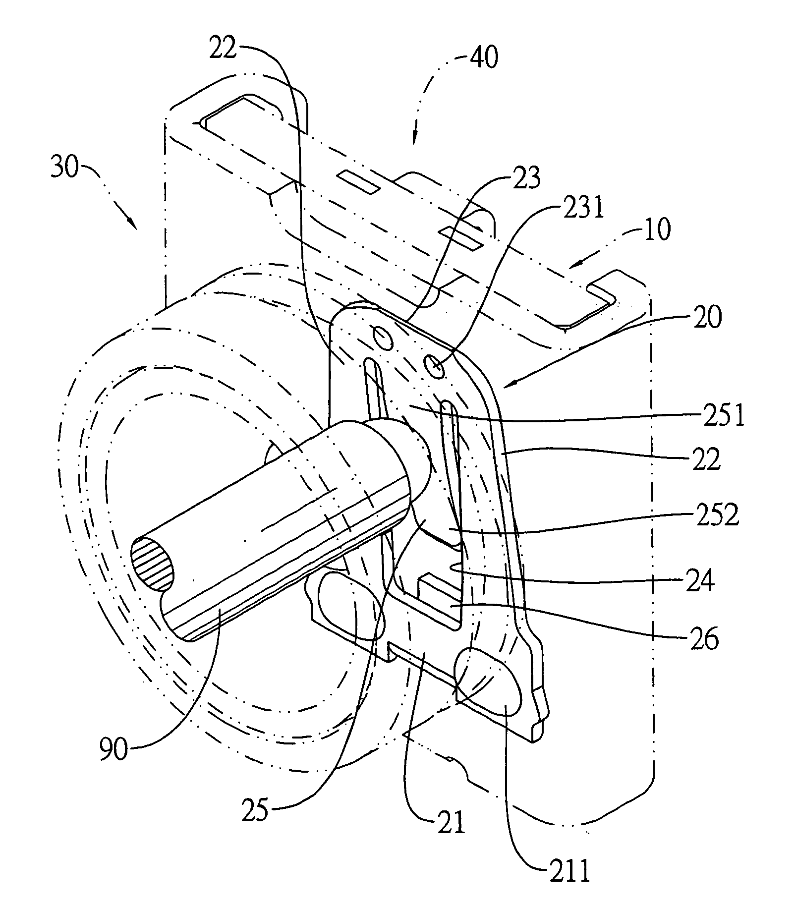
[0008]The main objective of the invention is to provide a RF coaxial connector that has an internal terminal with a specific configuration to providing sufficient resistance force to tightly contact a contact of an external connector for stable signal transmission.

Problems solved by technology

Therefore, the segment from the central portion to the free end of the internal terminal would not provide pin conductor with its resilient force.
Thus, the pin conductor loosely presses against the internal terminal, which makes the signal transmission between the connectors unstable.

Method used


Image

  • Radio frequency coxial connector
  • Radio frequency coxial connector
  • Radio frequency coxial connector

Examples


Embodiment Construction

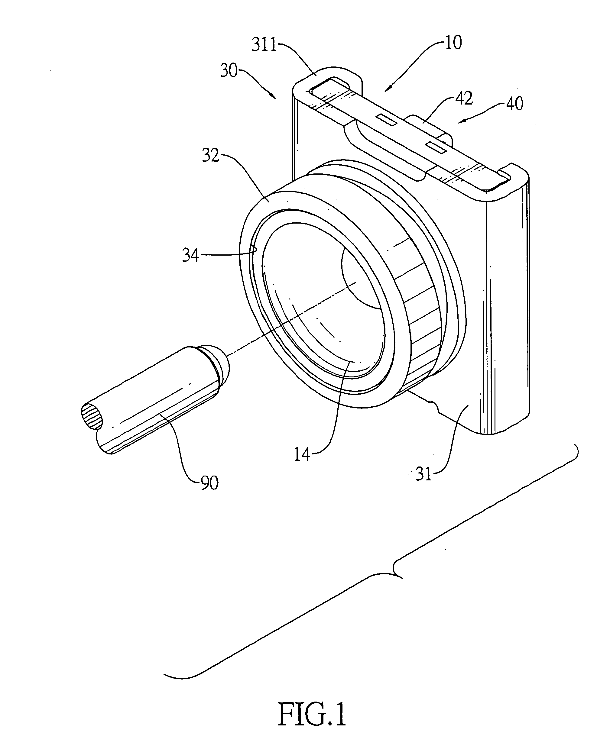
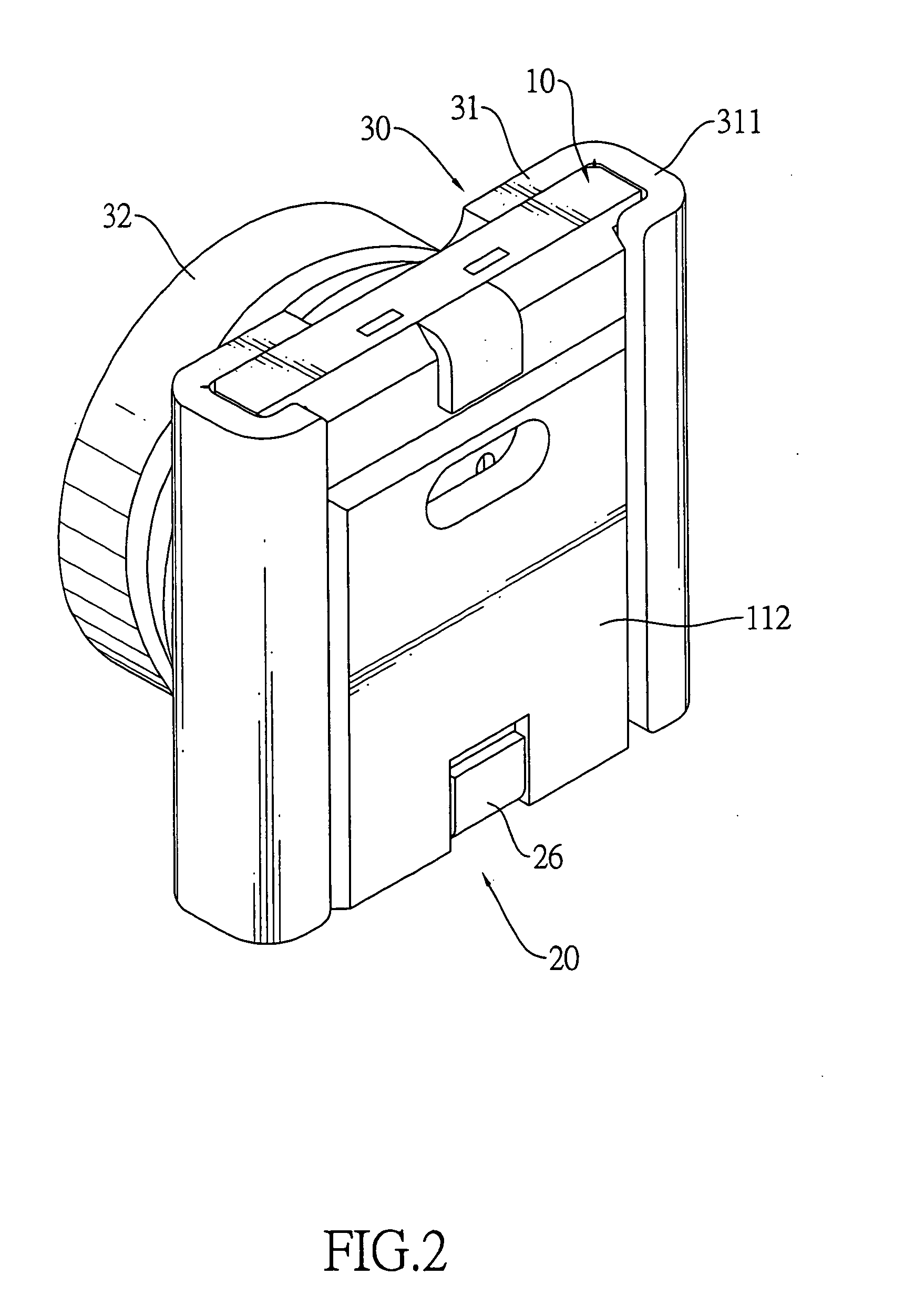
[0018]With reference to FIGS. 1 to 4 and 7, a RF coaxial connector in accordance with the present invention may be a receptacle connector mounted in an electronic device and may be connected to a corresponding connector in a coaxial connector. The corresponding connector may be a plug connector and has a pin conductor (90).

[0019]The RF coaxial connector comprises an insulative housing (10), an internal terminal (20), an external terminal (30) and a detecting terminal (40).

[0020]The insulative housing (10) has a base (11) and a socket (12).

[0021]The base (11) has a front (11), a rear (112) and a cavity (13).

[0022]The cavity (13) is defined in the base (11) and may have a front inner wall (131) and a rear inner wall (132) opposite to the front inner wall (131).

[0023]The socket (12) is formed on and protrudes forward from the front (111) of the base (10) and has a socket hole (14). The socket hole (14) is defined in the socket (12), communicates with the cavity (13) and may be adjacent...


PUM


Abstract

A RF coaxial connector has an insulative housing, an internal terminal and an external terminal. The insulative housing has a cavity. The internal terminal is mounted in the cavity and has a mounting section, two resilient arms protruding from the mounting section, a free section formed between the resilient arms and a contacting section protruding from the free section. The external terminal is mounted on the insulative housing. The internal terminal provides sufficient resistance force against a pin conductor of a corresponding connector engaged with the RF coaxial connector for stable signal transmission.

Description

BACKGROUND OF THE INVENTION[0001]1. Field of the Invention[0002]The present invention relates to a connector, and more particularly to a radio frequency (RF) coaxial connector that has an internal terminal with a specific configuration to providing sufficient resistance force to tightly contact a contact of an external connector for stable signal transmission.[0003]2. Description of Related Art[0004]RF coaxial connectors are used popularly in various electronic devices and may be connected to a coaxial cable mounted on an antenna for wireless signal transmission.[0005]U.S. Pat. No. 6,783,374 discloses a RF coaxial connector that has an insulative housing, an internal terminal and an external terminal. The insulative housing is composed of an upper casing and a bottom casing and has a socket. The internal terminal is formed by a stamping process, is mounted in the socket and has a connecting end and a free end. The connecting end is mounted securely on the insulative housing. The ext...

Claims


Application Information

Patent Timeline
IPC IPC(8): H01R9/05H01R24/38
CPCH01R24/46H01R2103/00H01R24/50
Inventor CHIEN, MIN-LUNGCHENG, KAI-RAYZHANG, HONG-WEIGUO, JIAN-GUANG
Owner ADVANCED CONNECTEK INC
Learn More