
HDMI optical cable and HDMI optical conversion device

Active Publication Date: 2019-08-15
AIM ELECTRONICS CO LTD
View PDF0 Cites 2 Cited by
  • Summary
  • Abstract
  • Description
  • Claims
  • Application Information

AI Technical Summary

Benefits of technology

The patent text discusses a problem with HDMI optical cables, which prevent the transmission of electrical signals. This results in the HDMI transmission device being unable to accurately detect whether the HDMI reception device can receive signals using the electric wire for TMDS video signal transmission. This can cause difficulties in video transmission and display, leading to a video not being displayed or distorted. The technical effects of this problem include reduced reliability and control in HDMI transmission devices, which can affect video display quality and performance.

Problems solved by technology

Therefore, there is a disadvantage that the HDMI transmission device cannot accurately detect whether the HDMI reception device can receive signals using the electric wire for TMDS video signal transmission that is used to transmit a video signal to the HDMI reception device.
However, in the conventional HDMI optical cable, an electrical signal cannot be physically transmitted and received, so that device connection cannot be detected since the electric wire for TMDS video signal transmission used for the device connection detection is replaced by the optical fiber wire.
Therefore, the HDMI transmission device having an HDMI output terminal cannot accurately determine whether the reception device including an HDMI terminal is operable and becomes uncontrollable within the HDMI transmission device, so that there are cases where normal signal transmission and video display cannot be performed.

Method used


Image

  • HDMI optical cable and HDMI optical conversion device
  • HDMI optical cable and HDMI optical conversion device
  • HDMI optical cable and HDMI optical conversion device

Examples


Embodiment Construction

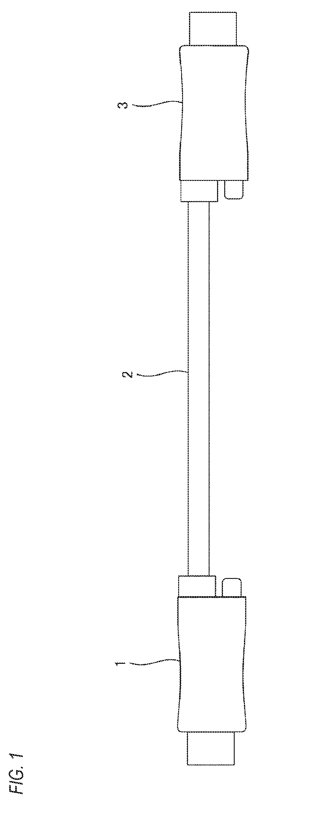
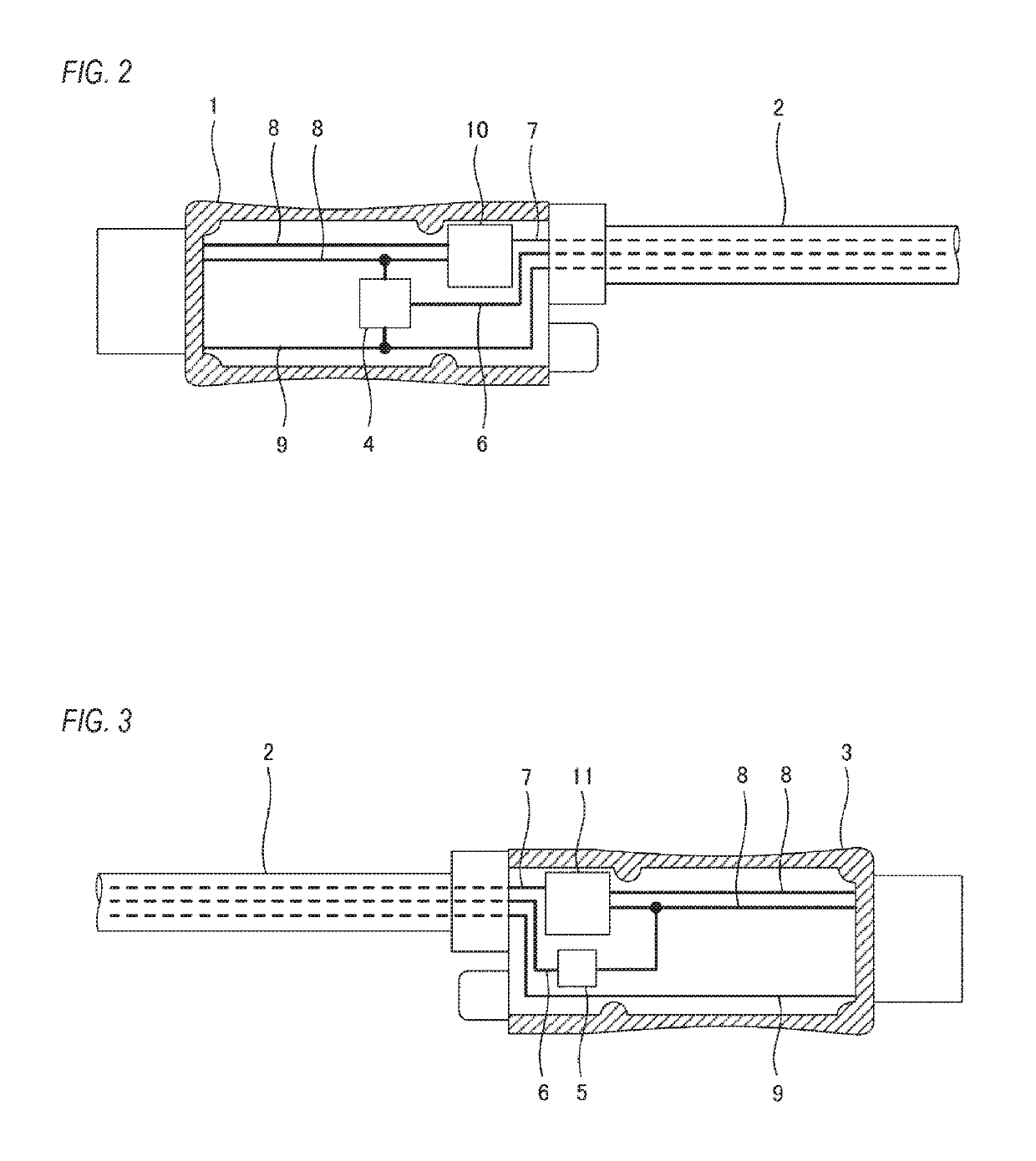
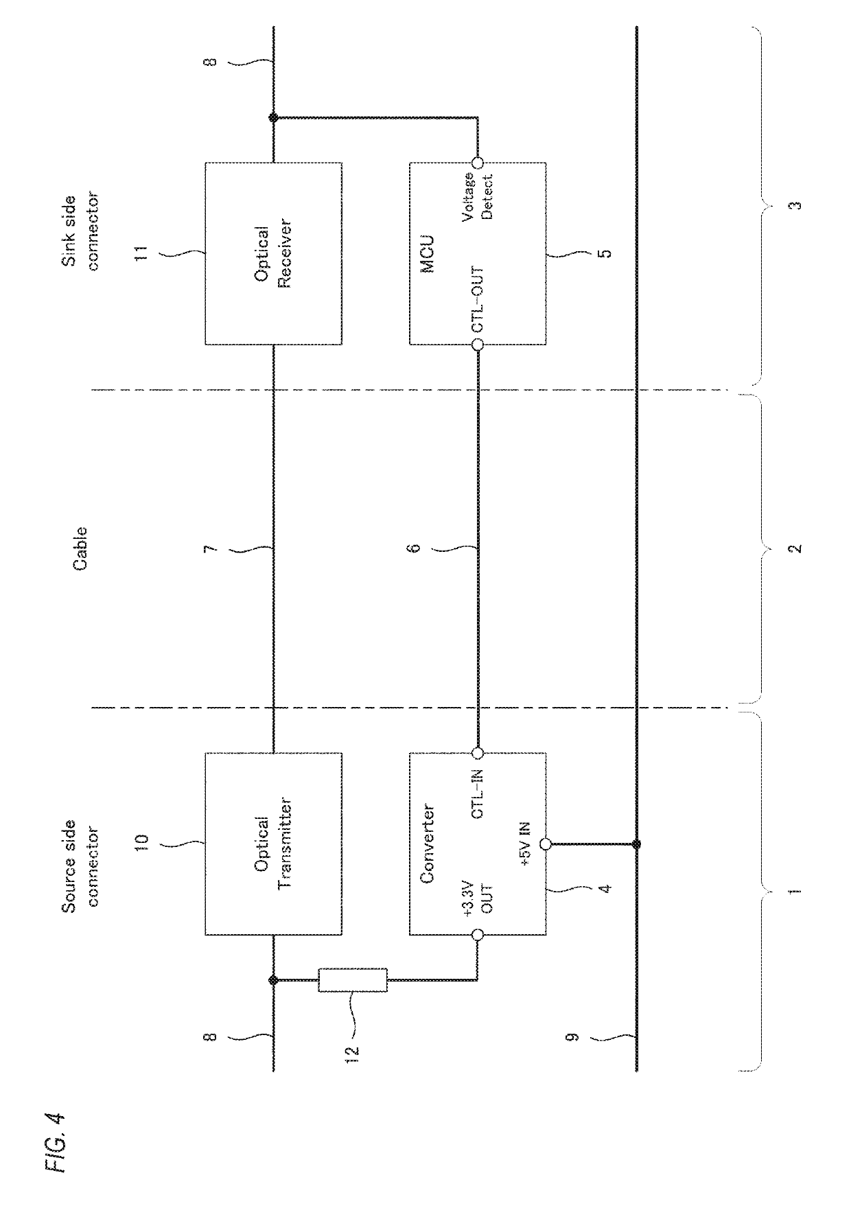
[0015]An HDMI optical cable illustrated in FIGS. 1 to 3 integrally includes a transmission device side connector 1 to be connected to an HDMI transmission device, a reception device side connector 3 to be connected to an HDMI reception device, and a cable 2 connecting the transmission device side connector 1 and the reception device side connector 3. The cable 2 includes an optical fiber wire 7 configured to transmit an RUB video signal and a clock signal from the HDMI transmission device to the HDMI reception device, a power supply line 9 configured to supply +5V power from the HDMI transmission device to the HDMI reception device, and a detection signal transmission dedicated line 6 configured to transmit a connection detection signal from the HDMI reception device to the HDMI transmission device. The power supply line 9 and the detection signal transmission dedicated line 6 are electric wires such as copper wires.

[0016]As illustrated in FIG. 2, one end of the optical fiber wire 7...


PUM


Abstract

Conventional HDMI optical cables are structured to be unable to normally transmit connection detection between HDMI transmission device and reception device, and unable to avoid a communication failure. Therefore, a phenomenon in which an image is distorted or does not appear occurs. By using an HDMI optical cable and anHDMI optical conversion device in which an electronic circuit switch having a device connection detection function, a voltage converter, a detection sensor, and a detection signal transmission-only wire are embedded in a connector and a cable, respectively, it becomes possible to stably perform connection detection and communication between HDMI transmission device and reception device, and show an image.

Description

TECHNICAL FIELD[0001]The present invention relates to a cable including an HDMI (registered trademark) connector and an interface of the connector, and a structure and performance inside the connector, and particularly relates to an HDMI optical cable having a structure that includes a device connection detection function inside a connector thereof to enable stable signal transmission.BACKGROUND ART[0002]An HDMI cable that connects an HDMI transmission device and an HDMI reception device includes a TMDS video transmission line that transmits a video signal and a clock signal, a DDC signal line that transmits EDID information of the HDMI reception device to the HDMI transmission device, a power supply line that supplies +5V power from the HDMI transmission device to the HDMI reception device, and an HPD signal line used for connection detection (so-called hot plug detection) of the HDMI reception device to the HDMI transmission device.[0003]The HPD signal line is typically connected ...

Claims


Application Information

Patent Timeline
IPC IPC(8): H04B10/2575H01R13/66G02B6/42H04N21/4363H04B10/66H04B10/50
CPCH04B10/25751H01R13/6691H01R13/6683G02B6/4201H04N21/43635H04B10/66H04B10/50G02B6/4416G02B6/4284H01R13/66G06F3/00G02B6/42H04N21/436G02B6/44H04N21/41H04B10/25
Inventor NAKAYAMA, EISHI
Owner AIM ELECTRONICS CO LTD
Learn More